
Gate Types and Gate Location: How to Choose
-
 Mohamed Aboelfotouh
- Sector : Plastic Injection
- Oct. 2, 2026, 4:06 p.m.
The gate is where the runner meets the part. Its type decides how the part is separated from the runner and what mark is left. Its position decides how the cavity fills: where the weld lines form, where air is trapped, and how the part shrinks and warps. Both decisions are made early and are expensive to change after the mold is built. This article compares the common gate types and gives the rules for choosing the position.
Six gate types compared
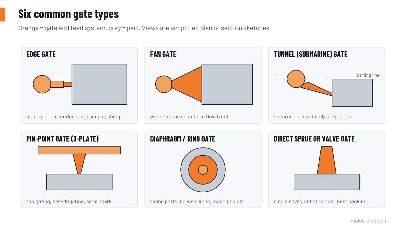
| Gate type | Typical use | Degating | Advantages | Limits |
|---|---|---|---|---|
| Edge (side) gate | General parts in two-plate molds | Manual or with a cutter | Simple to machine and to modify | Visible mark on the edge; extra operation |
| Fan gate | Wide, flat parts; parts that must stay flat | Manual or cutter | Even flow front, low orientation stress | Large gate to trim; wide scar |
| Tunnel (submarine) gate | Small and medium parts in automatic two-plate molds | Automatic at ejection | No operator, small mark on a side wall | Needs a flexible material or correct geometry; limited gate size |
| Pin-point gate | Three-plate molds, top gating, multi-cavity round parts | Automatic when the plates open | Gate in the centre of the part, small mark | Higher mold cost, more opening stroke, high shear in the gate |
| Diaphragm or ring gate | Tubes, sleeves, round parts needing roundness | Machined or punched off | No weld lines, uniform filling around a core | Trimming cost, large scrap |
| Direct sprue or valve gate | Single-cavity large parts; hot runner molds | Sprue cut off; valve gate leaves almost no mark | Lowest pressure loss, best packing | Large sprue mark, or the cost of a hot runner |
Gate dimensions
| Gate type | Thickness or diameter | Other dimensions |
|---|---|---|
| Edge | 50–80 % of the wall thickness | Width 2–4 × its thickness; land length 0.5–1.0 mm |
| Fan | 30–50 % of the wall at the land | Width up to the full part edge; land about 1 mm |
| Tunnel | 0.8–2.0 mm at the tip (about 30–70 % of the wall) | Tunnel at 30–50° to the parting line; cone with 10–20° included angle |
| Pin-point | 0.8–2.0 mm | Land 0.5–1.0 mm; small dimple around the gate to hide the vestige |
| Diaphragm | 0.3–1.5 mm | Land about 1 mm, uniform around the circumference |
| Direct sprue | Small end slightly larger than the machine nozzle bore; base up to about 1.5 × wall | Taper 1–2° per side; keep it as short as possible |
Two rules apply to every type. First, keep the land short: a long land causes pressure loss and early freezing. Second, cut the gate small and open it after the first trial. Steel can be removed easily and added only by welding.
Filled and viscous materials (glass-filled PA, PC) need gates toward the upper end of each range. Easy-flowing materials (PP, PE, PS) work toward the lower end.
Where to put the gate: eight rules
- Gate into the thickest section. Material must flow from thick to thin so the thick area can be packed while the gate is open. Gating into a thin wall and filling a thick boss at the end of flow gives sinks and voids.
- Keep flow lengths equal. Choose the point from which the distances to the far ends of the part are similar. This gives even pressure and avoids overpacking one side.
- Check the flow-length limit. Every material can only flow a certain distance for a given wall thickness. If the longest path exceeds it, add a gate or thicken the wall.
- Place weld lines where they do no harm. Each additional gate, core or hole produces a weld line. Move the gate so the lines fall away from visible faces, snap-fits and highly loaded areas.
- Avoid jetting. Do not let the material shoot into an open space. Aim the gate at a core pin or a wall close to it so the flow front forms at once.
- Think about the venting. The end of fill must be at the parting line or at a place where a vent or a vented pin can be added.
- Respect the appearance and function of the surface. No gates on cosmetic faces, sealing faces or sliding faces. Remember that the area around any gate has high residual stress.
- Consider orientation. Fibre-filled and semi-crystalline materials shrink differently along and across the flow. For a long part, gating from one end gives a uniform direction; gating in the middle of a flat disc gives radial flow and a tendency to dish.
Flow-length guide
The ratio of flow length to wall thickness is a quick check on whether one gate is enough. The values are approximate, for a 2 mm wall under normal conditions.
| Material | Flow length ÷ wall thickness |
|---|---|
| PP | 250–350 |
| PE-HD | 200–250 |
| PS | 200–250 |
| ABS | 150–200 |
| PA6, PA66 (unfilled) | 150–250 |
| POM | 100–250 |
| PMMA | 130–150 |
| PC | 80–130 |
Example: an ABS cover with a 2 mm wall and a longest flow path of 380 mm has a ratio of 190. That is at the limit for one gate, so the choice is two gates (with a weld line to position) or a 2.5 mm wall (ratio 152).
One gate or several
| Situation | Choice |
|---|---|
| Flow length within the limit, round or compact part | One gate, central if possible |
| Long, narrow part | One gate at an end, or a fan gate, for uniform orientation |
| Large flat part beyond the flow limit | Several gates; with a hot runner, sequential valve gates to push the weld line along and out |
| Part with a large window or core | Gate so the two fronts meet at a thick, hot place and close to a vent |
| Multi-cavity mold | Same gate type and size in every cavity, runner balanced by geometry |
Matching gate type to mold type and volume
| Mold concept | Usual gate | Comment |
|---|---|---|
| Two-plate, cold runner, low volume | Edge or fan | Cheapest mold; trimming by hand |
| Two-plate, cold runner, automatic | Tunnel | No trimming labour; check that the material tolerates the bend of the runner at ejection |
| Three-plate, cold runner | Pin-point | Central gating without a hot runner; runner falls separately |
| Hot runner, open nozzle | Pin-point at the nozzle tip | Small vestige; possible stringing or drooling with some materials |
| Hot runner, valve gate | Valve pin | Best surface, widest process window, highest cost |
Common mistakes
| Mistake | Result | Correction |
|---|---|---|
| Gate at the thin end "because it is hidden there" | Sinks and voids in the thick end | Gate into the thick section or core it out |
| Tunnel gate in a brittle or highly filled material | Gate breaks and stays in the tunnel | Shorten the tunnel, increase the cone angle, or use an edge gate |
| Unbalanced cavities corrected with different gate sizes | Cavities pack differently; dimensions vary between cavities | Balance the runner; keep the gates equal |
| Gate opposite an open space | Jetting marks | Redirect the gate at a wall or use an overlap gate |
| Gate land too long | High pressure loss, short shots, gate freezes early | Land of 0.5–1.0 mm |
| Gate size finalized before the trial | Welding needed to reduce it | Start small, open in steps |
Key takeaways
- Choose the gate type from the mold concept and the degating method: edge and fan for simple molds, tunnel and pin-point for automatic degating, valve gates for surface quality.
- Size the gate at 50–80 % of the wall for edge gates and 0.8–2.0 mm for tunnel and pin-point gates, with a short land.
- Put the gate in the thick section, balance the flow lengths, and decide where the weld lines and the last-filled point will be before the steel is cut.
- Use the flow-length ratio to decide early whether one gate is enough.
Related Articles
Mold Steel Selection by Production Volume and Resin
How to choose injection mold steel — P20, H13, stainless and high-hardness grades — from production volume, resin abrasiveness, corrosion and surface finish.
Hot Runner vs. Cold Runner: When Each One Pays Off
A cost and technical comparison of hot runner and cold runner injection molds, with a simple break-even calculation to support the decision.
Injection Molding Defects: A Troubleshooting Guide
Short shots, flash, sink marks, warpage, weld lines, burn marks, splay and jetting: causes and a structured order of corrective actions.
Injection Mold Cooling Design: Channel Layout and Cycle Time
Sizing and placing cooling channels in injection molds: diameter, pitch and depth rules, turbulent flow, circuit layout and their effect on cycle time.
Exploring the Plastic Injection Molding Process & Types
Learn about the plastic injection molding process, its types, and how it produces high-quality plastic parts for industries like automotive and electronics