
Injection Mold Cooling Design: Channel Layout and Cycle Time
-
 Mohamed Aboelfotouh
- Sector : Plastic Injection
- Oct. 2, 2026, 4:06 p.m.
In most injection molds, cooling takes more than half of the cycle. It also decides whether the part comes out flat or warped. Yet cooling channels are often drilled last, wherever the ejector pins and screws leave room. This article gives the rules for sizing, placing and connecting cooling channels, and a short calculation to check that the circuit can remove the heat.
How much heat, and how long
Two numbers frame the design: the cooling time the part needs and the heat the mold must remove per second.
Cooling time depends mainly on wall thickness. The plastic is a poor heat conductor, so heat from the middle of the wall must travel through the plastic itself before the steel can take it away. The time rises with the square of the wall thickness.
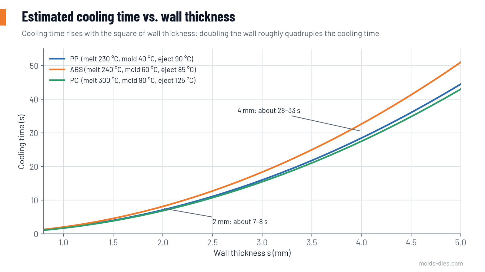
| Wall thickness (mm) | Approximate cooling time (s) |
|---|---|
| 1.0 | 2 |
| 1.5 | 4–5 |
| 2.0 | 7–8 |
| 3.0 | 15–18 |
| 4.0 | 28–33 |
These values assume the cavity surface stays at the set mold temperature. A badly cooled mold surface runs hotter than the water, and the real cooling time is longer. That is the part the mold designer controls.
Heat load is the mass of plastic per shot multiplied by the heat each kilogram gives up between melt temperature and ejection temperature, divided by the cycle time. Semi-crystalline materials give up more heat than amorphous ones.
| Material | Heat to remove (kJ per kg, approximate) |
|---|---|
| PP, PE-HD | 500–700 |
| PA6, PA66 | 500–650 |
| ABS, PS | 300–400 |
| PC | 350–450 |
Channel diameter, depth and pitch
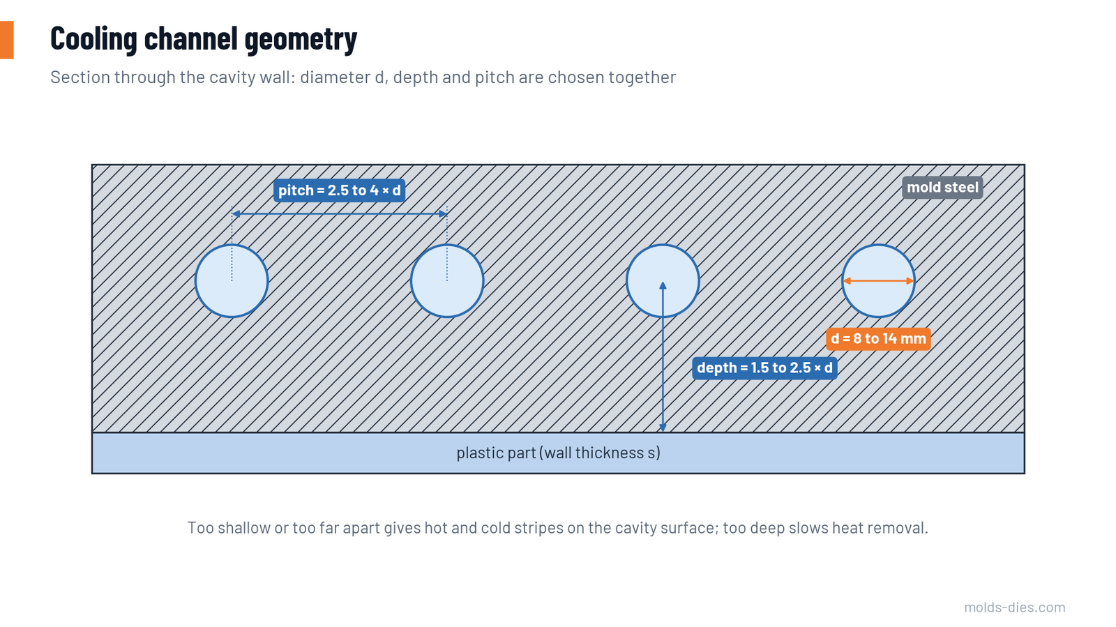
| Part wall thickness (mm) | Channel diameter d (mm) | Depth, channel centre to cavity surface | Pitch, centre to centre |
|---|---|---|---|
| Up to 2 | 8–10 | 1.5–2.5 × d | 2.5–4 × d |
| 2–4 | 10–12 | 1.5–2.5 × d | 2.5–4 × d |
| 4–6 | 12–14 | 1.5–2.5 × d | 2.5–4 × d |
The logic behind the table:
- Channels too close to the surface or too far apart give alternating cold and warm stripes on the cavity. This shows as gloss differences and uneven shrinkage.
- Channels too deep give an even surface temperature but respond slowly and remove less heat.
- Keep the same depth along the whole cavity. A channel that follows the part contour at constant distance is worth more than a larger straight channel that is near in one place and far in another.
- Keep at least 3–4 mm of steel between a channel and any ejector pin hole, screw or insert pocket, more in hardened steel under high injection pressure.
Turbulent flow is not optional
Water in slow, layered (laminar) flow takes up heat several times less effectively than water in turbulent flow. The measure is the Reynolds number: above about 4,000 the flow begins to be turbulent, and a value above 10,000 is the usual design target.
For water at 20 °C, the flow needed for a Reynolds number of 10,000 is roughly 0.47 litres per minute for each millimetre of channel diameter. Warm water is thinner and needs less.
| Channel diameter (mm) | Minimum flow at 20 °C (L/min) | Minimum flow at 60 °C (L/min) |
|---|---|---|
| 8 | 3.8 | 1.8 |
| 10 | 4.7 | 2.2 |
| 12 | 5.7 | 2.7 |
| 14 | 6.6 | 3.1 |
The second check is the temperature rise of the water between inlet and outlet. Keep it within 2–5 °C, and within 2–3 °C for precision parts. A larger rise means one end of the cavity is cooled by warmer water than the other.
Worked example
A PP part and runner weigh 0.12 kg per shot. The cycle is 20 seconds. The mold has four circuits of 10 mm channels.
| Quantity | Calculation | Result |
|---|---|---|
| Heat per shot | 0.12 kg × 550 kJ/kg | 66 kJ |
| Heat load | 66 kJ ÷ 20 s | 3.3 kW |
| Water flow for a 3 °C rise | 3.3 ÷ (4.18 × 3) | 0.26 kg/s = 15.8 L/min |
| Flow per circuit | 15.8 ÷ 4 | about 4 L/min |
| Turbulence check, 10 mm channel | needs 4.7 L/min at 20 °C, 2.2 at 60 °C | borderline with cold water; acceptable with water at 40 °C or above |
The result says: with chilled water, raise the flow to about 5 L/min per circuit or accept three circuits. The calculation takes five minutes and prevents a mold that can never reach its planned cycle.
Circuit layout
| Layout | Advantages | Risks |
|---|---|---|
| Series (one path through all channels) | Flow is the same everywhere and easy to verify | Water warms along the path; high pressure drop if the path is long |
| Parallel (branches from a manifold) | Low pressure drop, same inlet temperature for every branch | Flow divides unevenly; a partly blocked branch gets almost none, and nobody notices |
Practical rules:
- Use several short series circuits rather than one long circuit or many unbalanced parallel branches.
- Give each mold half its own circuits, and separate circuits for slides and large inserts, so their temperatures can be set independently.
- Put the inlet near the hottest area, usually near the gate.
- Avoid internal parallel branches. If you must use them, make the branches identical in length and diameter.
- Do not let hoses and quick couplings be the bottleneck. A coupling with a 6 mm bore on a 12 mm channel cancels the benefit of the larger channel.
- Mark every inlet and outlet on the mold and draw the circuit plan on the mold drawing.
Cooling the core
The core receives more heat per unit of surface than the cavity, because the part shrinks onto it and it has less steel to carry heat away. Cores that run hotter than the cavity pull the part into a warped shape. Options, from simple to advanced:
| Solution | Use |
|---|---|
| Baffle (a blade dividing a drilled hole) | Cores from about 12 mm diameter upward |
| Bubbler (a tube feeding water to the tip of a drilled hole) | Slender cores; better flow than a baffle |
| Thermal pin or high-conductivity copper-alloy insert | Cores too thin for water; moves heat to a cooled area |
| Spiral core insert | Large round cores |
| Conformal channels (built by additive manufacturing or by brazed layers) | Complex shapes where drilled channels cannot follow the contour |
Keeping it working
- Scale and rust insulate the channel wall. Even a thin layer cuts the heat transfer noticeably. Use treated water, and descale channels at each major service.
- Measure flow per circuit with a flow meter at mold approval, and record it. Repeat the measurement when cycle time or warpage drifts.
- Blow out the water before storing the mold.
Common mistakes
| Mistake | Effect |
|---|---|
| Channels placed after everything else | Hot spots near bosses and corners, longer cycle |
| One long circuit for the whole mold half | Temperature rise above 5 °C, uneven shrinkage |
| No core cooling | Warpage toward the hot side, sticking on the core |
| Same water temperature on core and cavity without checking | Part bends toward the hotter half |
| Flow never measured | Laminar flow in half the circuits |
Key takeaways
- Cooling time rises with the square of wall thickness; the mold can only add to it, not reduce it below the material's limit.
- Use channels of 8–14 mm, at a depth of 1.5–2.5 diameters and a pitch of 2.5–4 diameters, following the part contour.
- Check two numbers for every circuit: turbulent flow and a water temperature rise of 2–5 °C.
- Cool the core at least as well as the cavity, and measure the flow at approval.
Related Articles
Mold Steel Selection by Production Volume and Resin
How to choose injection mold steel — P20, H13, stainless and high-hardness grades — from production volume, resin abrasiveness, corrosion and surface finish.
Hot Runner vs. Cold Runner: When Each One Pays Off
A cost and technical comparison of hot runner and cold runner injection molds, with a simple break-even calculation to support the decision.
Injection Molding Defects: A Troubleshooting Guide
Short shots, flash, sink marks, warpage, weld lines, burn marks, splay and jetting: causes and a structured order of corrective actions.
Gate Types and Gate Location: How to Choose
A practical guide to choosing the gate type and gate position in injection molds: edge, fan, tunnel, pin-point, diaphragm and valve gates compared.
Exploring the Plastic Injection Molding Process & Types
Learn about the plastic injection molding process, its types, and how it produces high-quality plastic parts for industries like automotive and electronics