
Conformal Cooling in Injection Molds and Die Casting Inserts: Design Rules and Payback
-
 Mohamed Aboelfotouh
- Sector : Additive Manufacturing
- Oct. 9, 2026, 6:13 a.m.
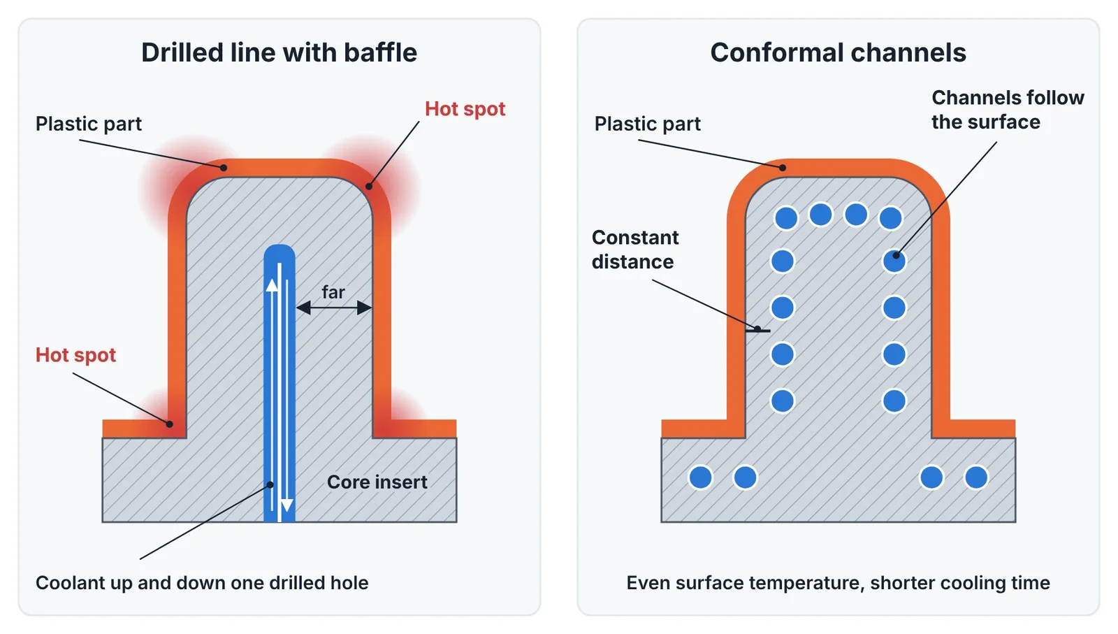
Cooling takes more than half of a typical injection molding cycle, and it decides warpage, sink and dimensional stability. Drilled cooling lines are straight, so in a curved or deep cavity their distance to the surface changes from point to point. Conformal cooling channels are printed inside the insert and follow the cavity at a constant distance. This article gives the design rules for those channels, the limits in die casting, and a method to calculate whether the extra cost is paid back.
Where conformal cooling pays
Conformal cooling removes hot spots. It pays where a hot spot is the reason for a long cycle or for rejects, and it adds nothing where drilled lines already cool the part evenly.
| Good candidates | Poor candidates |
|---|---|
| Deep or slender cores that drilled lines, baffles and bubblers cannot cool evenly | Flat or shallow parts with straight lines at uniform distance |
| Thick sections, bosses and gate areas that control the cooling time | Molds with short production runs |
| Parts rejected for warpage caused by uneven mold temperature | Cycles limited by the machine, the robot or the ejection, not by cooling |
| Multi-cavity molds where a few seconds are multiplied by millions of shots | Inserts too large for the build chamber and without a clear hot zone |
Before any design work, check what limits the present cycle. A filling and cooling simulation, or a thermal camera picture of the open mold, shows where the heat is. The drilled layout rules are covered in Injection Mold Cooling Design: Channel Layout and Cycle Time.
Channel size, pitch and distance
Three dimensions define a conformal layout: the channel diameter d, the pitch p between channel centres, and the distance c from the channel centre to the cavity surface. The widely used guideline values depend on the wall thickness of the plastic part.
| Part wall thickness | Channel diameter d | Pitch p (centre to centre) | Distance c (centre to cavity) |
|---|---|---|---|
| Up to 2 mm | 4–8 mm | 2–3 × d | 1.5–2 × d |
| 2–4 mm | 8–12 mm | 2–3 × d | 1.5–2 × d |
| 4–6 mm | 12–14 mm | 2–3 × d | 1.5–2 × d |
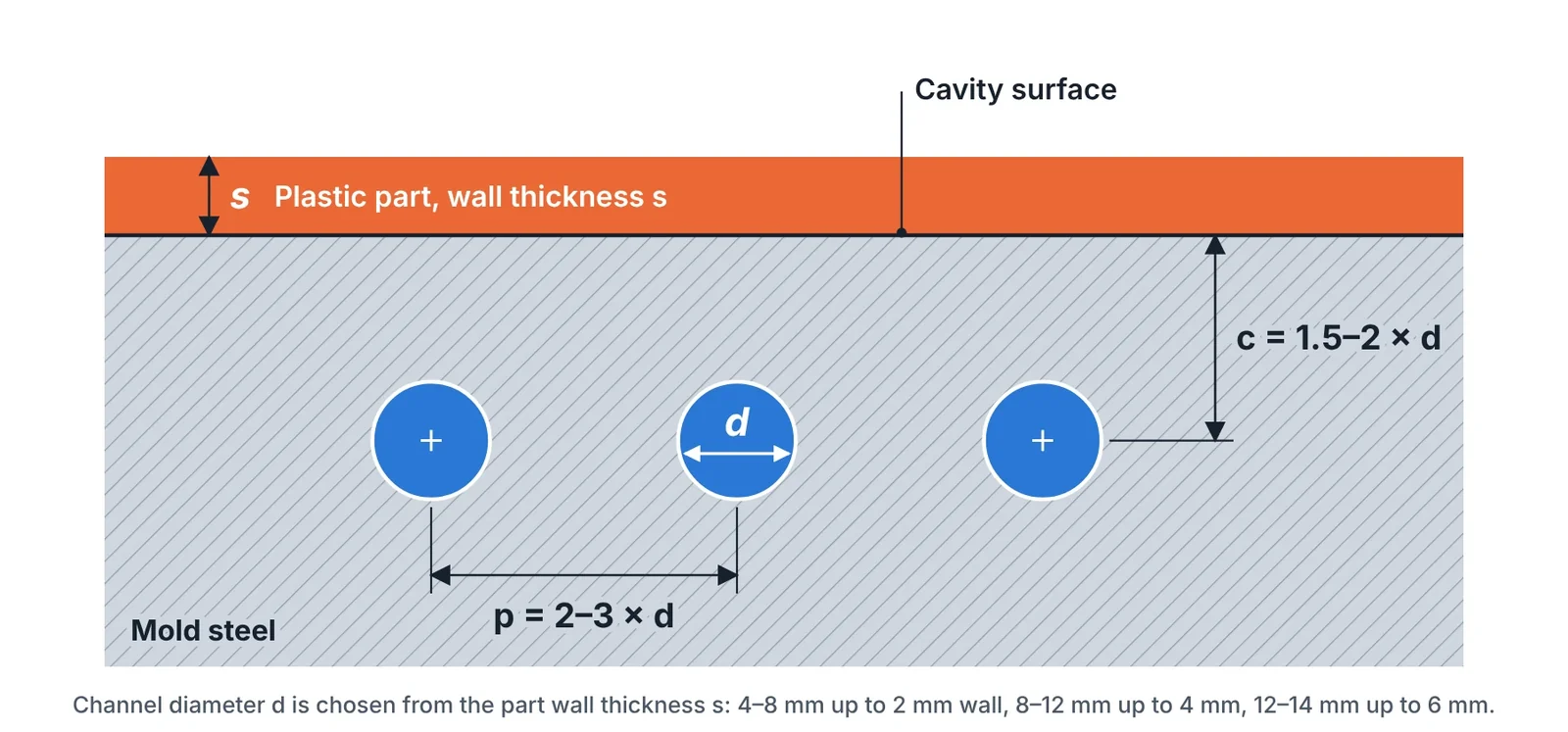
Closer channels give a more even surface temperature but weaken the steel between the channel and the cavity. Keep at least 2–3 mm of solid steel after machining and polishing, and check the section against the cavity pressure in highly loaded areas. Channels that are too far apart give a striped temperature pattern on the part.
Flow: keep it turbulent and keep circuits short
A channel only removes heat well when the flow is turbulent. The Reynolds number should be above 4,000 and preferably near 10,000 or more.
Re = 21,220 × Q / (d × ν)
Q is the flow in L/min, d the channel diameter in mm and ν the kinematic viscosity in mm²/s (about 1.0 for water at 20 °C and 0.47 at 60 °C).
Example. A circuit with d = 8 mm carries 6 L/min of water at 20 °C. Re = 21,220 × 6 / (8 × 1.0) ≈ 15,900, well into the turbulent range, at a velocity of about 2 m/s. With a temperature rise of 3 °C between inlet and outlet, this circuit removes about 1.25 kW.
- Temperature rise. Keep the difference between inlet and outlet below 2–3 °C for precision parts and below 5 °C in general. A larger rise means the circuit is too long or the flow too low.
- Parallel circuits of equal length. One long serial channel has a high pressure drop and a warm end. Several shorter circuits of the same length and section share the flow evenly.
- Pressure drop. The printed channel wall is rough, so the pressure drop is higher than in a drilled hole of the same size. Small diameters and many bends raise it quickly. Check that the temperature controller can deliver the flow at the available pressure, typically a few bar.
- Constant section. Where a channel changes shape, keep the flow area constant so the velocity does not drop.
Rules that come from the printing process
- Self-supporting sections. A horizontal round channel prints without internal supports up to about 8 mm diameter. Larger channels use a teardrop or pointed-roof section, because supports inside a channel cannot be removed.
- Powder removal. Every channel must be open at both ends. Avoid dead ends, sharp bends and diameters below 3–4 mm, which trap powder and later collect scale.
- Smooth paths. Use bend radii of at least 1.5 × d and no abrupt junctions.
- Corrosion. Maraging steel 1.2709 is not stainless. Use treated water with an inhibitor, plate the channels with electroless nickel, or print the insert in a corrosion-resistant mold steel.
- Filtration. Small channels block easily. Fit a filter in the supply and flush the circuits at every maintenance, as described in the preventive maintenance program.
- Proof test. Flow-test and pressure-test each circuit after heat treatment and again after final machining. Record the flow at a fixed pressure as a reference for later checks.
Hybrid inserts
Printing cost rises with volume and build height. A hybrid insert keeps the printed volume small: the lower part is a machined block with drilled supply lines, and only the upper part with the conformal channels is printed on top of it.
- The base is machined flat and clamped in the printer as the build plate. Its drilled lines are aligned with the printed channels.
- Base and powder should be compatible grades, for example a maraging or precipitation-hardening base under 1.2709, so that one heat treatment suits both.
- Place the joint in a low-stress zone, away from the cavity surface and from sealing diameters.
- Savings of 30–60 % of the printing cost are common on tall inserts.
Die casting inserts
High-pressure die casting adds thermal shock and much higher cavity pressure. The benefits are real: lower die surface temperature, less soldering, less spray and shorter solidification in thick sections. The limits are stricter.
| Point | Injection mold | HPDC die |
|---|---|---|
| Distance, channel wall to cavity | From about 1 × d | Not below 10–12 mm for water; drilled practice is 20–25 mm |
| Main risk | Corrosion and blockage | Thermal fatigue crack reaching the channel |
| Material | Maraging 1.2709 or stainless mold steel | H13-type where it can be printed; maraging for cores and small inserts |
| Coolant | Water | Water, oil, or pulsed water with air purge |
Maraging steel is aged at about 490 °C. Where the die surface runs hotter than that for long periods, the steel overages and softens, and heat checking starts earlier than in H13. It works well in core pins, sprue spreaders and local inserts that are strongly cooled. The mechanisms are described in Die Life in HPDC: Heat Checking, Soldering and How to Delay Them.
Calculating the payback
The extra cost of a conformal insert is paid back by machine time. The number of shots to break even is:
N = ΔC / (Δt × R / 3600)
ΔC is the extra cost of the insert set, Δt the cycle time saved in seconds and R the machine hour rate.
Example. A two-cavity mold runs at 32 s. Simulation shows 24 s with conformal cores. The printed cores cost 6,000 USD more than drilled ones and the machine rate is 40 USD/h.
- Saving per shot = 8 × 40 / 3600 = 0.089 USD
- Break-even = 6,000 / 0.089 = 67,500 shots, or 135,000 parts
- At 24 s per shot this is 450 machine hours, about four weeks of two-shift production

The calculation counts machine time only. Lower scrap from warpage and released machine capacity add to the gain, and they are often the larger part. For a mold that will run fewer shots than the break-even number, conformal cooling is justified only if it solves a quality problem that cannot be solved another way.
Common mistakes
| Mistake | Result | Correct approach |
|---|---|---|
| Adding conformal cooling without finding the hot spot | Cost with no cycle gain | Simulate or measure first |
| One long serpentine circuit | High pressure drop, warm outlet end | Parallel circuits of equal length |
| Channels too small | Blockage after months of production | Minimum 4 mm, filtered and treated water |
| Laminar flow | Channel present but ineffective | Check Reynolds number at the real flow rate |
| Printing the whole insert | Unnecessary build cost | Hybrid build on a machined base |
| Untreated water in maraging steel | Rust, reduced flow, leaks | Inhibitor, nickel plating or stainless grade |
Key takeaways
- Conformal cooling pays where a hot spot controls the cycle or causes warpage. Find the hot spot before designing channels.
- Size channels by part wall thickness: pitch 2–3 × d and distance to the cavity 1.5–2 × d, with turbulent flow and a temperature rise below 2–3 °C.
- Design for the process: self-supporting sections, open ends for powder removal, corrosion protection and a proof test of every circuit.
- Calculate the break-even in shots from the extra cost, the seconds saved and the machine rate, and use hybrid inserts to cut the printed volume.
Related Articles
Small Batches: Print the Part, Print the Tool, or Cut the Tool?
Break-even calculation for small batches: 3D printed parts, printed mold inserts, aluminum molds and steel molds, with routes for metal and sheet metal parts.
Repairing Molds and Dies with Laser Cladding and Directed Energy Deposition
Mold and die repair by TIG, laser welding and laser cladding compared: heat-affected zone, dilution, filler choice, repair procedure and when to replace.
Printing Tool Steel: Maraging, H13 and What Happens After the Build
Printable tool steels compared, with the full post-processing route: stress relief, age hardening, machining allowance, polishing limits and surface treatment.
3D Printed Mold Inserts for Short-Run Injection Molding
How to design and run 3D printed polymer mold inserts for 10 to 100 molded parts: materials, draft, gates, process settings, insert life and failure modes.
Additive Manufacturing for Toolmakers: Processes, Materials and Where Each Fits
The additive manufacturing processes that matter in a tool shop: what each one makes, its accuracy and materials, and which mold and die jobs it suits.
Injection Mold Cooling Design: Channel Layout and Cycle Time
Sizing and placing cooling channels in injection molds: diameter, pitch and depth rules, turbulent flow, circuit layout and their effect on cycle time.