Printing Tool Steel: Maraging, H13 and What Happens After the Build
-
 Mohamed Aboelfotouh
- Sector : Additive Manufacturing
- Oct. 9, 2026, 6:16 a.m.
A printed steel insert is not finished when the build ends. It comes out of the machine welded to a plate, rough, stressed and, in most cases, not yet at working hardness. The steel grade decides how easily it prints, and the steps after the build decide whether it fits, polishes and lasts. This article compares the printable tool steels and sets out the post-processing route from build plate to finished insert.
Why carbon is the problem
In laser powder bed fusion each track of metal melts and solidifies in a fraction of a second. A carbon tool steel such as H13 transforms directly to hard, untempered martensite while the layers below are still shrinking. High hardness, low ductility and high residual stress together produce cracks, sometimes during the build and sometimes days later.
Maraging steel avoids this. It contains almost no carbon (below 0.03 %), so its martensite is soft and tough when it forms. The steel is printed in this soft state and then hardened by ageing at a moderate temperature, without quenching. That is why maraging steel 1.2709 became the standard material for printed tooling.
The printable grades
| Grade | Type | Hardness as built | Hardness after heat treatment | Printability | Typical use |
|---|---|---|---|---|---|
| 1.2709 (18Ni300) | Maraging steel | 33–37 HRC | 50–54 HRC | Very good | Injection mold inserts, die casting cores and small inserts |
| Stainless precipitation-hardening mold steel | Corrosion-resistant maraging type | About 30–35 HRC | 46–50 HRC | Very good | Inserts with water channels, corrosive plastics such as PVC |
| 17-4PH (1.4542) | Stainless, precipitation-hardening | About 30–35 HRC | 38–44 HRC | Good | Low-wear inserts, fixtures, prototype tooling |
| H13 (1.2344) | Hot-work tool steel, 0.4 % C | 50–58 HRC, brittle | 44–52 HRC after tempering | Difficult; needs a heated build plate | Die casting inserts, hot-work tooling |
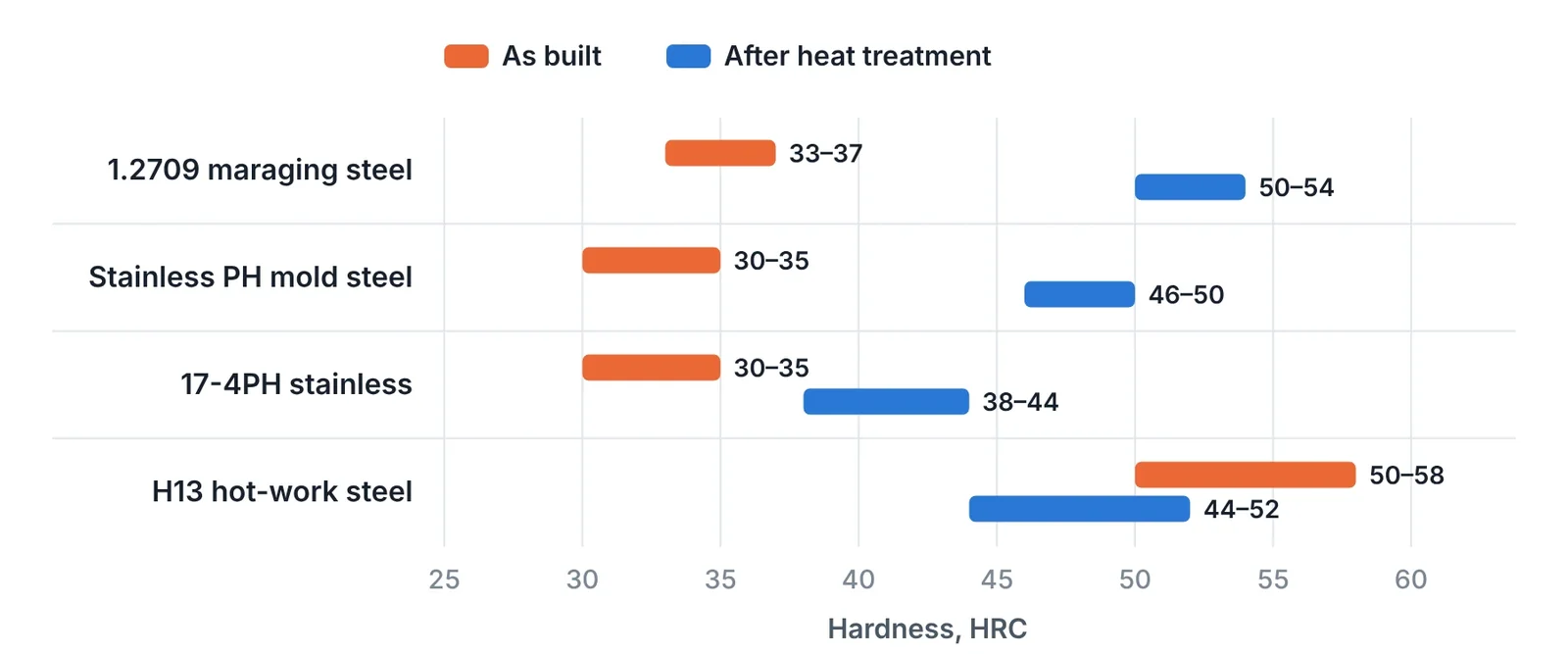
Three practical differences follow from the table.
- Maraging steels are machined soft and hardened last. At 33–37 HRC the as-built part mills and drills easily. Ageing then brings it to working hardness with very little distortion.
- H13 needs heat during the build. A build plate heated to 200 °C or more, and in some machines far higher, keeps the part above the temperature at which cracks form. Not every machine or bureau offers this.
- Thermal conductivity is lower than expected. Printed 1.2709 conducts about 15 W/m·K as built and about 20 W/m·K after ageing, against roughly 25 for H13 and 30 or more for pre-hardened mold steel. Conformal channels compensate by being closer to the surface. For inserts that need the highest heat removal, copper alloys such as CuCrZr can also be printed.
From build plate to finished insert
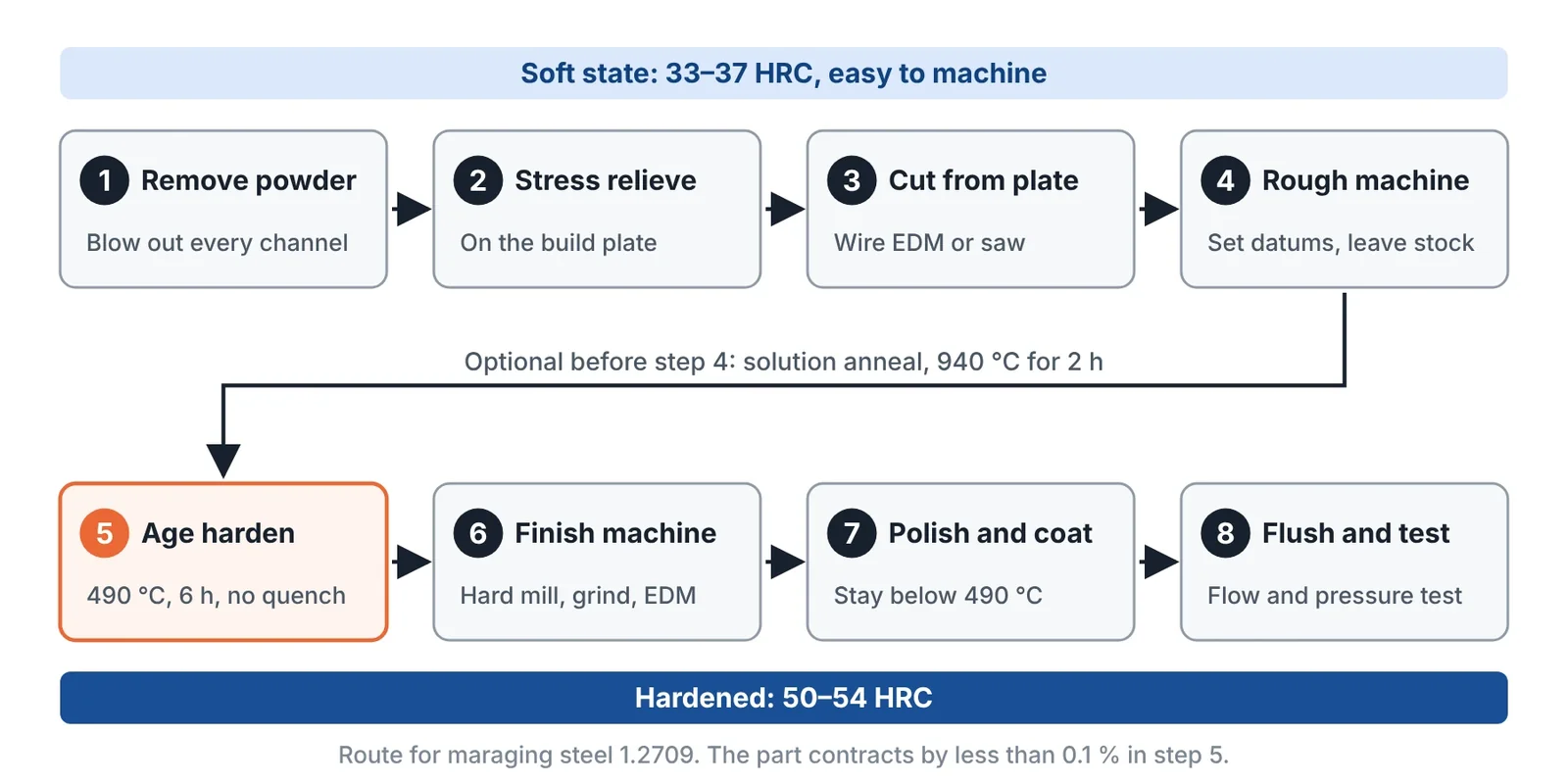
- Remove powder. Clear the build chamber and blow out every channel while the part is still on the plate. Powder left in a channel sinters during heat treatment and cannot be removed afterwards.
- Stress relieve on the plate. Residual stress is released by heating before the part is cut off. If the part is cut off first, it distorts. For H13, stress relieving at about 600–650 °C is essential. For maraging steel, the solution anneal or the ageing cycle does the same job.
- Cut from the plate. Use wire EDM or a band saw and leave stock on the bottom face.
- Solution anneal (optional). About 940 °C for two hours makes the structure uniform in all directions. It is used when toughness and consistent polishing matter.
- Rough machine in the soft state. Establish datums and remove most of the stock while the hardness is low.
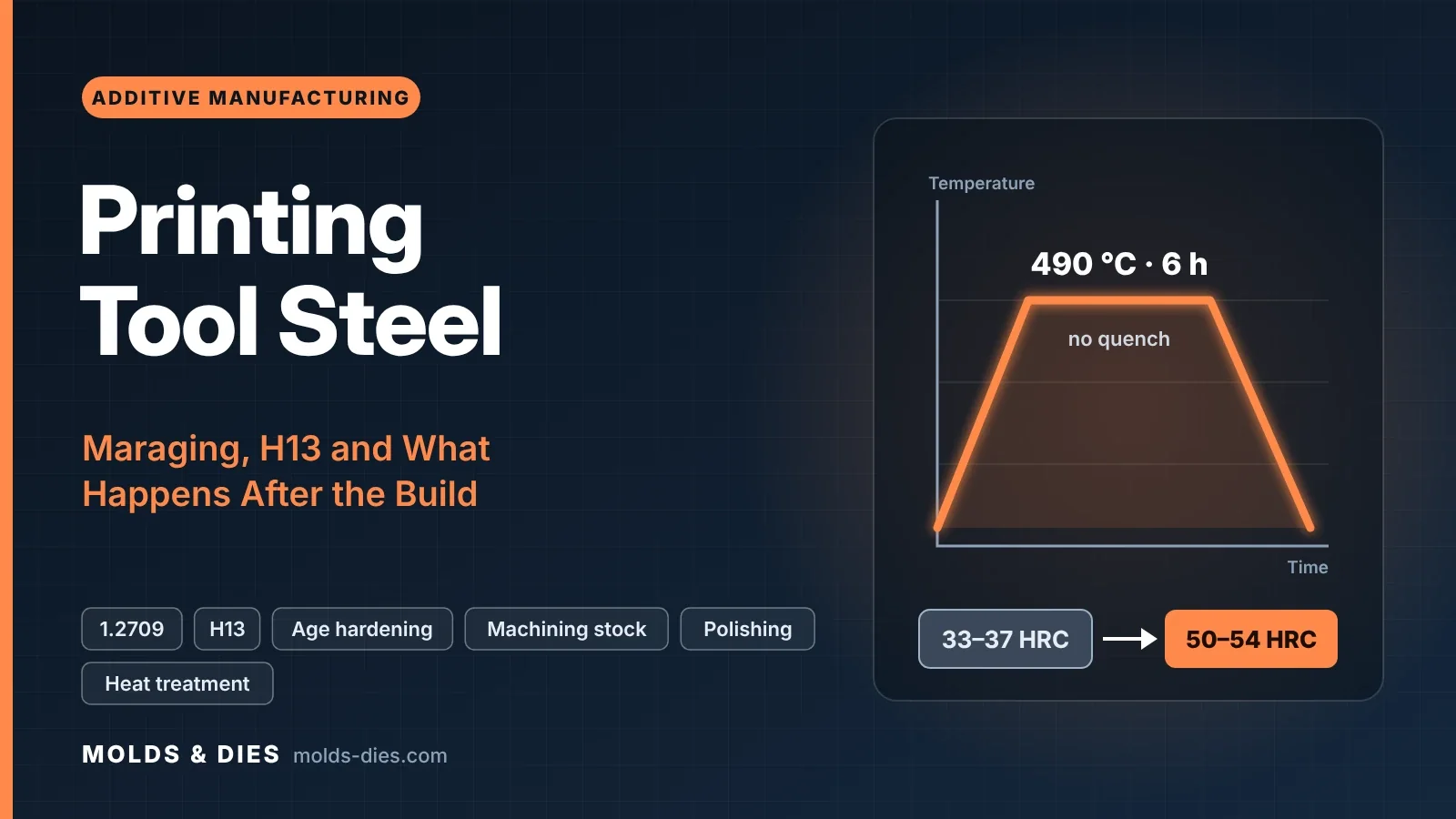
- Age harden. 490 °C for six hours gives 1.2709 its peak hardness of about 54 HRC. There is no quench. The part contracts slightly and uniformly, by less than 0.1 %.
- Finish machine. Hard mill, grind or EDM the fits, shut-offs and cavity to final size. The choice between milling and EDM follows the same logic as for wrought steel, described in Hard Milling vs. EDM for Mold Cavities.
- Polish, texture or coat.
- Flush and test. Flush the channels, then flow-test and pressure-test each circuit.
For H13 the route is different: stress relieve, cut off, then either double temper at 550–600 °C to reach the target hardness or fully harden and temper as for a wrought insert. Full hardening gives the most uniform structure and also the most distortion, so more stock is needed.
Machining allowance and datums
| Surface | Allowance | Reason |
|---|---|---|
| Cavity and core surfaces | 0.3–0.5 mm | Removes roughness and the porous skin zone |
| Fits, shut-offs, sealing diameters | 0.3–0.5 mm | Printed tolerance is not sufficient |
| Bottom face on the plate | 1–3 mm | Cutting loss and distortion |
| Large or thin inserts | 0.5–1 mm | Distortion from residual stress |
| Threads and O-ring grooves | Machine from solid | Printed threads and grooves leak |
- Design clamping and datum features into the print: flat pads, a reference bore, or sacrificial tabs that are cut off at the end.
- Check the wall between channel and finished surface after the allowance is removed, not before.
- Scan or measure the part before machining and best-fit the program to the actual shape, so that the stock is spread evenly.
Density, porosity and polishing
A good build is more than 99.5 % dense. The remaining pores are small, typically 10–50 µm, and they are concentrated just below the surface where the contour and the fill tracks meet. Three consequences matter in a mold.
- Polishing. Polishing can open a pore and leave a pinhole. Printed maraging steel reaches a good technical polish. For optical or high-gloss surfaces it is a risk, and a wrought remelted steel is the safer choice for that face.
- Texturing. Printed steel etches differently from standard mold steels. Ask the texturing supplier for a test on a printed sample before committing a cavity.
- Leak paths. A chain of pores between a channel and the cavity is rare but possible in thin walls. The pressure test finds it.
Removing 0.3–0.5 mm from the surface takes away most of the near-surface porosity. Where a flawless surface is essential, the insert can be built as a hybrid with the visible face in wrought steel, or the printed part can be hot isostatically pressed to close internal pores.
Surface treatment and repair
| Treatment | On maraging 1.2709 | On printed H13 |
|---|---|---|
| Nitriding | Possible at 450–480 °C; can be combined with the ageing step | As for wrought H13 |
| PVD coating | Suitable; keep the coating temperature at or below the ageing temperature | Suitable |
| Electroless nickel | Used on cavities for corrosion and in channels against rust | Possible |
| Welding | Welds well with maraging filler; re-age locally | Preheat and temper as for wrought H13 |
Any treatment above 490 °C overages maraging steel and lowers its hardness. This rules out high-temperature CVD coatings. The treatments themselves are compared in Surface Treatments for Tooling: Nitriding, PVD and When Each Fits.
Which grade for which tool
| Application | Recommended grade | Note |
|---|---|---|
| Injection mold core or cavity insert with conformal cooling | 1.2709 | Treat the water or plate the channels |
| Insert for corrosive plastics or untreated water | Stainless precipitation-hardening mold steel | Slightly lower hardness, no rust in channels |
| Insert for glass-filled plastics | 1.2709 with nitriding or PVD | 52–54 HRC alone wears at gates |
| HPDC core pin, sprue spreader, local insert | 1.2709, strongly cooled | Softens if the surface stays above 490 °C |
| HPDC cavity insert | Printed H13 where available | Best resistance to heat checking |
| Fixture, gripper, prototype tool | 17-4PH | Lowest cost, adequate hardness |
Common mistakes
| Mistake | Result | Correct approach |
|---|---|---|
| Cutting the part from the plate before stress relief | Distortion beyond the machining stock | Heat treat on the plate first |
| Powder left in channels before heat treatment | Permanently blocked circuit | Blow out and check every channel on the plate |
| Finish machining before ageing | Size change after hardening | Rough soft, age, then finish |
| CVD coating or high-temperature treatment on maraging steel | Loss of hardness | Stay at or below 490 °C |
| Specifying a mirror polish on a printed face | Pinholes | Hybrid insert with wrought steel on the optical face |
| Ordering H13 from a machine without build plate heating | Cracked build | Confirm the process, or use maraging steel |
Key takeaways
- Maraging steel 1.2709 prints easily because it has almost no carbon. It is machined at 33–37 HRC and aged at 490 °C to 50–54 HRC with minimal distortion.
- H13 can be printed only with a heated build plate and careful heat treatment. It remains the choice for die casting cavities.
- The route is fixed: remove powder, stress relieve on the plate, cut off, rough machine, harden, finish, test the channels.
- Leave 0.3–0.5 mm on every functional face, keep treatments below the ageing temperature, and do not rely on printed steel for optical polish.
Related Articles
3D Printed Mold Inserts for Short-Run Injection Molding
How to design and run 3D printed polymer mold inserts for 10 to 100 molded parts: materials, draft, gates, process settings, insert life and failure modes.
Additive Manufacturing for Toolmakers: Processes, Materials and Where Each Fits
The additive manufacturing processes that matter in a tool shop: what each one makes, its accuracy and materials, and which mold and die jobs it suits.
Small Batches: Print the Part, Print the Tool, or Cut the Tool?
Break-even calculation for small batches: 3D printed parts, printed mold inserts, aluminum molds and steel molds, with routes for metal and sheet metal parts.
Repairing Molds and Dies with Laser Cladding and Directed Energy Deposition
Mold and die repair by TIG, laser welding and laser cladding compared: heat-affected zone, dilution, filler choice, repair procedure and when to replace.
Conformal Cooling in Injection Molds and Die Casting Inserts: Design Rules and Payback
Design rules for conformal cooling channels in printed mold inserts: diameter, pitch, distance to cavity, flow, hybrid inserts, HPDC limits and payback.