Hard Milling vs. EDM for Mold Cavities: When to Use Each
-
 Mohamed Aboelfotouh
- Sector : Machining
- Oct. 2, 2026, 6:40 p.m.
Twenty years ago, almost every hardened mold cavity was finished by sinker EDM. Today, stiff high-speed machines and coated carbide tools can mill steel at 50–60 HRC to final size and finish. Hard milling is usually faster and leaves a better surface, but it cannot reach everything. The practical question for each cavity is which features to mill and which to leave for EDM. This article gives the criteria.
How the two processes compare
| Hard milling | Sinker EDM | |
|---|---|---|
| How material is removed | Cutting with a rotating tool | Electrical sparks between a shaped electrode and the workpiece |
| Hardness limit | Up to about 62–65 HRC with suitable tools | None; any conductive material |
| Geometry limit | Tool must reach: limited by depth-to-diameter ratio and by the internal corner radius | Any shape an electrode can be made for, including sharp internal corners and deep narrow ribs |
| Preparation | CAM programming | Electrode design, machining of one or more electrodes, plus CAM for them |
| Surface | Cut surface with regular tool marks; compressive residual stress if cut correctly | Cratered matt surface with a recast layer; tensile stress and possible micro-cracks |
| Typical finish | Ra 0.2–0.8 µm | Ra 0.4–3.2 µm in normal work; finer with long finishing times |
| Polishing afterwards | Less work; no hard skin to remove | Recast layer must be removed for high polish |
| Accuracy | Depends on machine, tool deflection and tool wear | Depends on electrode accuracy, wear and spark gap control |
| Unattended running | Good, with tool measurement and replacement tools | Very good; long burns run overnight |
The decision criteria
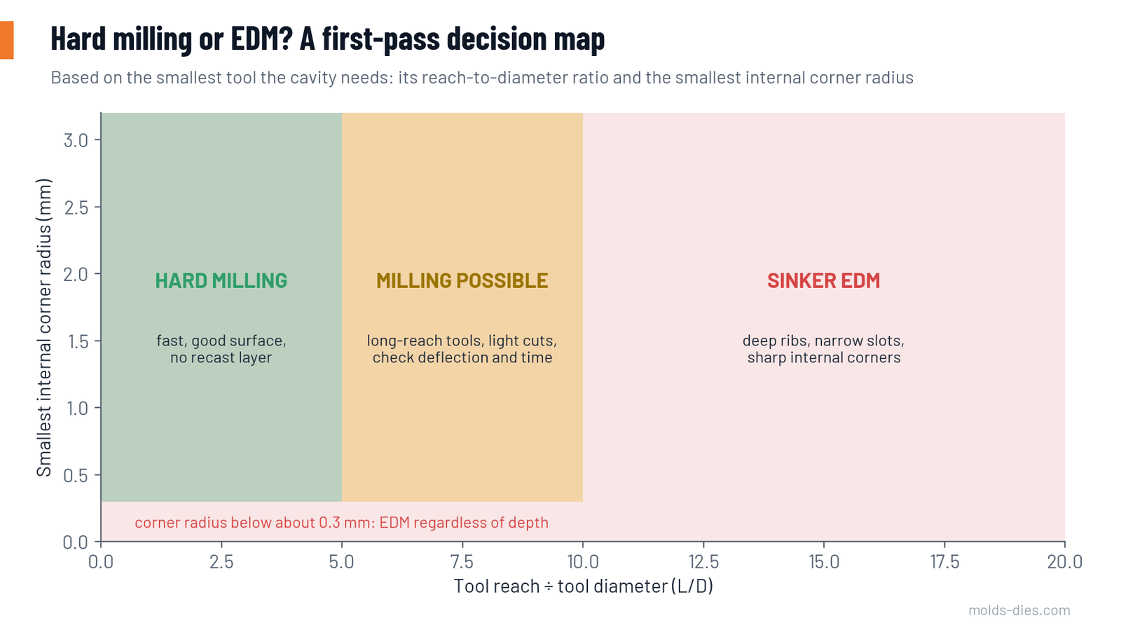
1. Reach-to-diameter ratio. Find the smallest tool the feature needs (from its narrowest width or smallest corner radius) and divide the required reach by that tool's diameter.
| Reach ÷ diameter | Assessment |
|---|---|
| Up to 5 | Hard milling without difficulty |
| 5–10 | Possible with tapered-neck or long-reach tools, light cuts and time; compare cost with EDM |
| Above 10 | EDM, unless the wall has enough draft for a strongly tapered tool |
2. Internal corner radius. A milled internal corner cannot be sharper than the tool radius. Radii below about 0.3 mm in hardened steel mean very small tools with short life. If the part design allows it, enlarge the radius. A corner radius slightly larger than the tool radius is best, so the tool does not stop and dwell in the corner.
3. Ribs and slots. A rib in the plastic part is a narrow slot in the steel. As a guide, slots deeper than about 5–8 times their width are EDM features.
4. Surface requirement. For a high-gloss polish, a milled surface saves polishing time and avoids the recast layer. For a matt textured surface specified as an EDM finish, the EDM surface is the final surface and no polishing is needed.
5. Material and section. Very hard, brittle materials and thin steel walls that would deflect or vibrate under cutting forces favour EDM, which applies no mechanical force.
6. Quantity of identical features. One electrode can burn many identical cavities; milling time multiplies with the number of cavities.
What hard milling needs
| Element | Requirement |
|---|---|
| Machine | Stiff structure, high-speed spindle (15,000 rev/min or more for small tools), thermal stability, good look-ahead control |
| Tool holder | Shrink-fit or high-precision collet; run-out below about 0.005 mm at the tool tip |
| Tools | Coated fine-grain carbide ball-nose and corner-radius cutters with a strong neck; CBN for fine finishing in some cases |
| Stick-out | As short as possible; use several tool lengths and machine each depth zone with the shortest tool that reaches |
| Tool paths | Constant engagement; no full-width slotting; arcs into and out of the cut; rest machining with decreasing tool sizes |
| Cooling | Usually dry with an air blast; thermal shock from liquid coolant cracks carbide edges in hard steel |
| Stock after heat treatment | Small and uniform: about 0.3–0.5 mm from rough milling before hardening |
Typical finishing parameters in steel at 50–55 HRC, for a ball-nose cutter of 6 mm: cutting speed 100–180 m/min at the effective diameter, feed per tooth 0.03–0.06 mm, depth and step-over 0.05–0.2 mm depending on the scallop height required.
What EDM needs
| Element | Requirement |
|---|---|
| Electrodes | Graphite for speed and large shapes; copper for fine finish and small details |
| Undersize | Each electrode is smaller than the cavity by the spark gap and orbit: typically 0.1–0.3 mm per side for roughing, 0.03–0.1 mm for finishing |
| Number of electrodes | One or two roughing and one or two finishing electrodes per shape, because electrodes wear, especially at corners |
| Flushing | Dielectric must carry particles out of the gap; deep ribs need orbiting, lifting cycles or flushing holes |
| Positioning | A reference system so electrodes and workpiece are located repeatably |
Surface finish scale. EDM finishes are often specified by the VDI 3400 grades:
| VDI grade | Ra (µm) |
|---|---|
| 12 | 0.4 |
| 18 | 0.8 |
| 24 | 1.6 |
| 30 | 3.2 |
| 36 | 6.3 |
Each step toward a finer finish roughly doubles the finishing time. Specify only as fine as the part needs.
Recast layer. The surface melted and resolidified by the sparks is hard and brittle, and under it is a heat-affected zone. Its thickness ranges from a few micrometres after fine finishing to 20–30 µm or more after roughing. For highly loaded tools such as die-casting dies and stamping punches, remove it by polishing or fine finishing and follow with a stress-relief temper.
The usual answer: combine them
The most economical route for most cavities is:
- Rough mill in the soft condition, leaving uniform stock.
- Heat treat.
- Hard mill everything the tools can reach within a reach-to-diameter ratio of about 5–8, to final size.
- EDM only the remaining features: deep ribs, sharp internal corners, narrow slots, fine details and lettering.
- Polish or texture.
This keeps EDM electrodes small and few, and it removes most of the polishing work.
A quick comparison for one feature
A rib slot 2 mm wide and 20 mm deep with 1° draft in steel at 52 HRC:
| Route | Steps | Comment |
|---|---|---|
| Hard milling | 2 mm tapered tool with 20 mm reach (ratio 10); many light passes | Long cycle; risk of tool breakage at the bottom; possible, but at the limit |
| EDM | Mill two graphite electrodes (minutes each); burn rough and finish | Predictable; runs unattended; surface needs light polishing in the draw direction |
Here EDM is the safer choice. Change the slot to 4 mm wide and 16 mm deep (ratio 4) and hard milling becomes the faster route.
Design changes that move features into the milling zone
| Change | Effect |
|---|---|
| Larger internal corner radii | Larger, stiffer tools |
| More draft on deep walls and ribs | Allows tapered tools with thick necks |
| Split the cavity into inserts | Deep features become open and reachable from the side |
| Lower, thicker ribs | Smaller reach-to-diameter ratio |
Raise these with the part designer early. A radius changed from 0.2 to 0.5 mm can remove an electrode set from the job.
Common mistakes
| Mistake | Result |
|---|---|
| EDM used for the whole cavity out of habit | Extra electrodes, burning time and polishing |
| Hard milling with long tools at normal parameters | Chatter marks, broken tools, oversize walls from deflection |
| Liquid coolant in hard milling | Thermal cracking of the cutting edges |
| Uneven stock after heat treatment | Tool overload in the heavy areas |
| Recast layer left on a highly stressed die surface | Early cracking in service |
| Finer EDM finish specified than needed | Finishing time doubled for no benefit |
Key takeaways
- Geometry decides: mill what a tool can reach at a reach-to-diameter ratio up to about 5, consider milling up to 10, and use EDM beyond that and for sharp internal corners.
- Hard milling gives a better surface with no recast layer and less polishing; EDM reaches any shape and applies no force.
- Most cavities are best made by milling first and using EDM only for the features that remain.
- Small changes to radii, draft and insert splits at the design stage can remove EDM work entirely.
Related Articles
Trochoidal Milling and Chip Thinning in Tool Steel
How trochoidal (dynamic) milling works, how to compensate for radial chip thinning, and starting parameters for roughing tool steel.
Reading Tool Wear: Flank, Crater, Notch and Built-Up Edge
How to recognize the main cutting tool wear patterns — flank, crater, notch, built-up edge, chipping and thermal cracks — and the correction for each.
Wire EDM: Number of Passes, Surface Finish and Accuracy
How rough cut and skim cuts determine wire EDM accuracy and surface finish, with typical values for passes, offsets, corner radius and recast layer.
Milling Speeds and Feeds: How to Calculate and Adjust
The formulas for spindle speed, table feed and metal removal rate in milling, starting values by material, and how to adjust them at the machine.
Types of Chips: Understanding Their Meaning for Optimal Machining
Learn about the different types of chips formed during machining processes and how understanding chip formation can optimize your manufacturing operations
Climb Milling vs Conventional Milling: A Comparative Analysis and Application Recommendations
Compare climb and conventional milling techniques to improve machining surface finish, accuracy, and tool wear management. Learn the best applications for each method
How to Estimate the Cost of a Mold or Die
A structured method for estimating tooling cost: material, standard parts, design and machining hours, heat treatment, trials, overhead and margin.