
Wire EDM: Number of Passes, Surface Finish and Accuracy
-
 Mohamed Aboelfotouh
- Sector : Machining
- Oct. 2, 2026, 6:40 p.m.
Wire EDM cuts punches, die openings, inserts and stripper plates from hardened steel with a thin wire and no cutting force. The accuracy and surface it delivers depend mostly on one decision: how many passes are made. One rough cut is fast and adequate for clearance openings. Precision punches and dies need the rough cut plus several skim cuts, and each skim adds time. This article explains what each pass does, what else affects accuracy, and how to specify the work so you pay only for what the part needs.
Rough cut and skim cuts
The rough cut (main cut) separates the part from the block with high spark energy. It leaves a surface with a relatively thick recast layer, a slight taper or barrel shape through the thickness, and a contour that has moved a little as internal stresses were released.
Skim cuts (trim cuts) follow the same contour with a smaller offset and lower energy. Each one removes a few hundredths of a millimetre or less, corrects the shape, improves the finish and thins the recast layer.
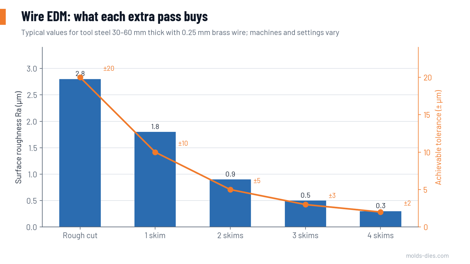
| Passes | Surface roughness Ra (µm) | Typical tolerance (mm) | Recast layer | Typical use |
|---|---|---|---|---|
| Rough cut only | 2.5–3.2 | ±0.015–0.020 | 10–25 µm | Clearance openings, stripper windows, rough blanks |
| 1 rough + 1 skim | 1.6–2.0 | ±0.010 | Reduced | General die components, punch holders |
| 1 rough + 2 skims | 0.8–1.0 | ±0.005 | A few µm | Cutting punches and die openings |
| 1 rough + 3 skims | 0.4–0.6 | ±0.003 | Thin | Precision dies, mold inserts with fits |
| 1 rough + 4 or more skims | 0.2–0.3 | ±0.002 | Minimal | Fine-blanking tools, carbide dies, sealing fits |
The values are typical for tool steel 30–60 mm thick on a modern machine in a temperature-controlled room. Older machines, tall workpieces and poor flushing all shift them toward the coarser side.
What a pass costs
Rough cutting speed is quoted as area per minute: cut length × workpiece thickness ÷ time. On tool steel with 0.25 mm brass wire, 100–250 mm² per minute is a normal range.
Example. A punch with a 200 mm perimeter cut from a 50 mm thick block:
| Step | Calculation | Time |
|---|---|---|
| Area to cut | 200 × 50 | 10,000 mm² |
| Rough cut at 150 mm²/min | 10,000 ÷ 150 | 67 min |
| Two skim cuts | each roughly 25–35 % of the rough-cut time | 35–45 min |
| Total for ±0.005 mm and Ra 0.8–1.0 | about 1 h 50 min | |
| With four skim cuts | about 2 h 30 min |
The EDM Wirecut Cutting Speed/Time Calculator on this site estimates the time from your own values. The point for the designer: asking for Ra 0.3 where Ra 0.8 would work adds 30–40 % to the wire time of every part.
Wire diameter and the smallest inside radius
The wire cannot cut an internal corner sharper than its own radius plus the spark gap.
| Wire diameter (mm) | Smallest inside corner radius after skims (mm) | Use |
|---|---|---|
| 0.30 | about 0.18–0.20 | Thick parts, highest cutting speed |
| 0.25 | about 0.15–0.18 | Standard for die work |
| 0.20 | about 0.12–0.15 | Finer detail |
| 0.10–0.15 | about 0.07–0.10 | Small radii and narrow slots; slow; limited workpiece height |
On drawings for parts cut with standard wire, specify inside radii of 0.2 mm or larger wherever function allows. Matching punch corners should carry the corresponding outside radius so the clearance stays constant around the corner.
What affects accuracy besides the number of passes
1. Internal stress in the workpiece. When the wire opens a block, stresses from heat treatment and grinding are released and the material moves. This is the most common cause of out-of-tolerance wire-cut parts.
- Temper the steel properly: two or three tempers, and for D2-type steels the high tempering range, which leaves less stress and less retained austenite.
- Start from a hole inside the block, not from the edge, so the frame stays closed.
- Make the rough cut around all openings first, let the part relax, then make the skim cuts.
- For punches, leave holding tabs and cut them last. For large openings, remove most of the material with a relief cut or by drilling before the final contour.
2. Flushing. The dielectric must remove particles from the gap. Nozzles should sit close to the top and bottom faces. On stepped or hollow workpieces the nozzles cannot seal; cutting speed must be reduced, and accuracy and wire breakage both suffer. Where possible, wire cut before the block is stepped or pocketed.
3. Workpiece height. In tall cuts the wire bows backward and the wall can become slightly barrel-shaped or hollow. Skim cuts correct it. Expect more skims for the same tolerance above about 80–100 mm.
4. Temperature. Dielectric, machine and workpiece must be at a steady temperature. A block that comes warm from grinding and cools in the tank changes size during the cut.
5. Corners. The wire lags in direction changes and rounds or undercuts corners. Machines reduce speed and energy in corners automatically if the corner strategy is switched on. Sharp outside corners can be improved with a small loop outside the contour.
6. Taper cutting. Die relief angles and tapered inserts are cut by tilting the wire. Accuracy is lower than in straight cuts, and it falls as the angle and the height increase. Keep the precise part of a die opening as a straight land and put the taper below it.
Surface integrity
The recast layer is hard and brittle and carries tensile stress. In ordinary tool steel components, two or more skim cuts reduce it to a few micrometres, which is acceptable for most uses. For highly loaded tools:
- use at least two or three skims on cutting edges;
- polish or lightly hone the cutting edge;
- stress temper after wire cutting, about 25 °C below the last tempering temperature.
Carbide needs extra care. The cobalt binder can be dissolved by electrolysis in the water dielectric, leaving a weak surface. Use a generator mode designed to prevent electrolysis, keep the exposure time short, and make enough skim cuts to remove the affected layer.
Matching passes to components
| Component | Passes | Comment |
|---|---|---|
| Stripper plate windows, clearance holes | 1 | Size is not critical |
| Punch holder and backing plate pockets | 1 + 1 | Location fits |
| Cutting punches and die openings, sheet over 1 mm | 1 + 2 | Clearance tolerance about ±0.005 mm |
| Cutting punches and dies, thin sheet below 0.5 mm | 1 + 3 | Small clearances need tighter size control |
| Mold inserts and cores with shut-off fits | 1 + 3 | Fit and sealing against flash |
| Carbide dies, fine-blanking tools, lamination dies | 1 + 4 or more | Edge quality and life |
| Extrusion die openings | 1 + 1 or 1 + 2 | Bearings are polished afterwards |
Specifying wire EDM work
Put the following on the drawing or the order, and let the operator choose the technology from it:
- Tolerance on the wire-cut contour, and which features it applies to.
- Surface roughness required, as Ra.
- Minimum inside corner radius allowed.
- Land length and taper angle for die openings.
- Material and hardness, and whether the block has been stress relieved.
- Any requirement for recast layer removal or stress tempering afterwards.
Do not write "four cuts" on a drawing. Write the result you need. The same result may need three passes on one machine and five on another.
Common mistakes
| Mistake | Result |
|---|---|
| One tolerance and finish for all wire-cut features | Hours of unnecessary skim cuts on clearance openings |
| Starting the cut from the block edge | Block opens up; contour moves |
| Skimming immediately after the rough cut on stressed material | Size drifts after the part is released |
| Sharp inside corners on the drawing | Cannot be made; clearance uneven at corners |
| Wire cutting after pockets and steps are milled | Poor flushing, wire breaks, taper |
| No stress temper on cutting tools | Edge chipping from the brittle surface layer |
Key takeaways
- The rough cut separates the part; each skim cut improves size, shape and finish, and adds roughly a quarter to a third of the rough-cut time.
- Two skims give about ±0.005 mm and Ra 0.8–1.0 µm, which suits most punches and dies.
- Stress in the block, flushing and temperature decide whether the nominal accuracy is reached.
- Specify tolerance, roughness and minimum radius per feature, and keep fine finishes for the features that need them.
Related Articles
Trochoidal Milling and Chip Thinning in Tool Steel
How trochoidal (dynamic) milling works, how to compensate for radial chip thinning, and starting parameters for roughing tool steel.
Reading Tool Wear: Flank, Crater, Notch and Built-Up Edge
How to recognize the main cutting tool wear patterns — flank, crater, notch, built-up edge, chipping and thermal cracks — and the correction for each.
Hard Milling vs. EDM for Mold Cavities: When to Use Each
A decision guide for finishing hardened mold and die cavities: when hard milling is faster and better, and when sinker EDM is still required.
Milling Speeds and Feeds: How to Calculate and Adjust
The formulas for spindle speed, table feed and metal removal rate in milling, starting values by material, and how to adjust them at the machine.
Types of Chips: Understanding Their Meaning for Optimal Machining
Learn about the different types of chips formed during machining processes and how understanding chip formation can optimize your manufacturing operations
Climb Milling vs Conventional Milling: A Comparative Analysis and Application Recommendations
Compare climb and conventional milling techniques to improve machining surface finish, accuracy, and tool wear management. Learn the best applications for each method