Reading Tool Wear: Flank, Crater, Notch and Built-Up Edge
-
 Mohamed Aboelfotouh
- Sector : Machining
- Oct. 2, 2026, 6:41 p.m.
A used cutting edge is a record of what happened in the cut. The position and shape of the wear show whether the speed was too high or too low, whether the grade was too hard or too soft, and whether heat or mechanical load did the damage. Machinists who look at the edge before throwing the insert away can correct the cause. Those who only replace it repeat the same life on the next edge. This article describes six wear patterns, their causes and the correction for each.
Where to look
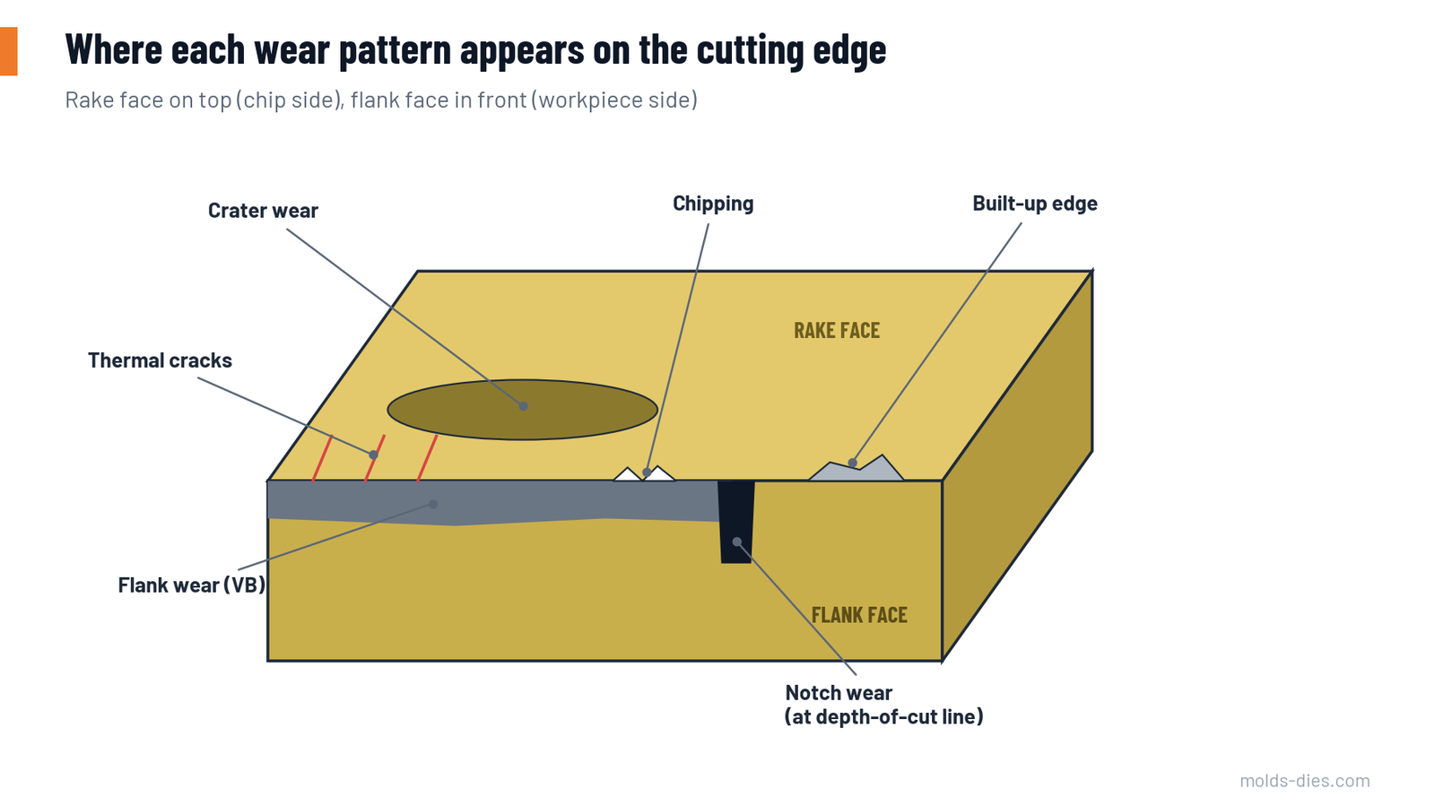
| Surface | What it is | What wears it |
|---|---|---|
| Flank face | The face that looks at the newly cut surface | Rubbing against the workpiece |
| Rake face | The face the chip slides over | Heat and pressure from the chip |
| Cutting edge | The line between them | Mechanical load, impact, adhesion |
Use a loupe of 10–20× magnification and good light. Look at the edge before cleaning it: built-up material is part of the evidence.
The six patterns
1. Flank wear
An even, matt wear land on the flank face, parallel to the cutting edge.
This is the normal, predictable wear mode and the one you want. It is caused by abrasion from hard particles in the workpiece.
| If it develops too fast | Action |
|---|---|
| Cutting speed too high | Reduce speed by 10–20 % |
| Grade not wear-resistant enough | Choose a harder grade or a thicker, more wear-resistant coating |
| Feed very low, edge rubbing | Increase feed |
| Abrasive workpiece (cast skin, hard inclusions, filled materials) | More wear-resistant grade; remove the skin with a tougher insert first |
2. Crater wear
A hollow on the rake face, a short distance behind the cutting edge.
The chip heats the rake face to the point where tool material diffuses into the chip. It is typical of machining steel at high speed. A deep crater weakens the edge until it breaks.
| Action |
|---|
| Reduce cutting speed first, then feed |
| Use a grade with an aluminum-oxide coating layer, which insulates against heat and diffusion |
| Use a more positive geometry to lower chip pressure |
| Apply coolant to the rake face where the operation allows |
3. Notch wear
A deep, local groove at the depth-of-cut line, where the edge leaves the workpiece surface.
At that point the edge cuts through the hardest part of the material: a work-hardened layer from the previous pass, forging or casting skin, or scale. It is common in stainless steels and heat-resistant alloys.
| Action |
|---|
| Vary the depth of cut from pass to pass so the notch does not form at one place |
| Use a smaller entering angle (45° or a round insert), which spreads the load along the edge |
| Choose a tougher grade with a thin coating applied at low temperature, and a sharp edge |
| Reduce cutting speed |
4. Built-up edge
Workpiece material welded to the cutting edge. It grows, breaks away and takes pieces of the coating and edge with it. The machined surface is rough and torn.
It forms when the temperature in the cut is too low for the chip to flow cleanly, and in sticky materials: aluminum, low-carbon steel, stainless steel.
| Action |
|---|
| Increase cutting speed: this is one of the few wear problems solved by going faster |
| Use a sharper, more positive geometry |
| Use a smooth, thin coating or an uncoated polished edge for aluminum |
| Improve lubrication (richer coolant concentration, or minimum-quantity lubrication) |
5. Chipping
Small pieces broken out of the cutting edge, leaving a ragged line.
The cause is mechanical: the edge is too brittle or too sharp for the load it sees.
| Cause | Action |
|---|---|
| Interrupted cut, hard spots, inclusions | Tougher grade; stronger edge preparation (hone or chamfer) |
| Vibration | Shorten the overhang; improve clamping; change speed |
| Chips re-cut or jammed | Improve chip evacuation; change the chip breaker |
| Built-up edge breaking away | See pattern 4 |
| Feed too high at entry or exit | Reduce feed when entering and leaving the cut |
6. Thermal cracks
Fine cracks at right angles to the cutting edge, like the teeth of a comb. They appear mainly in milling.
Each tooth heats in the cut and cools out of it. With intermittent coolant the temperature swing is large, and the surface cracks from thermal fatigue. Pieces between the cracks eventually break out.
| Action |
|---|
| Apply coolant copiously and continuously, or not at all. In milling steel and hardened steel, dry cutting with an air blast is usually better |
| Choose a tougher grade designed for milling |
| Reduce cutting speed and feed per tooth |
Two end states
If the patterns above are ignored, the edge ends in one of two ways:
- Plastic deformation: the edge is pressed down or bulges because heat has softened it under high pressure. Reduce speed and feed, or choose a harder, more heat-resistant grade.
- Breakage: the insert fractures. It is usually the final stage of excessive flank wear, a deep crater or notch, or severe chipping. The original cause is destroyed with the edge, which is why edges should be changed and examined before this point.
Quick reference
| Pattern | Main cause | Speed | Feed | Grade |
|---|---|---|---|---|
| Flank wear (too fast) | Abrasion, speed | Lower | Raise if very low | Harder |
| Crater wear | Heat on rake face | Lower | Lower | Oxide-coated |
| Notch wear | Hard surface layer | Lower | — | Tougher, sharp |
| Built-up edge | Temperature too low, adhesion | Raise | Raise | Sharp, smooth coating |
| Chipping | Mechanical overload | — | Lower at entry | Tougher |
| Thermal cracks | Temperature cycling | Lower | Lower | Tougher milling grade |
When to change the edge
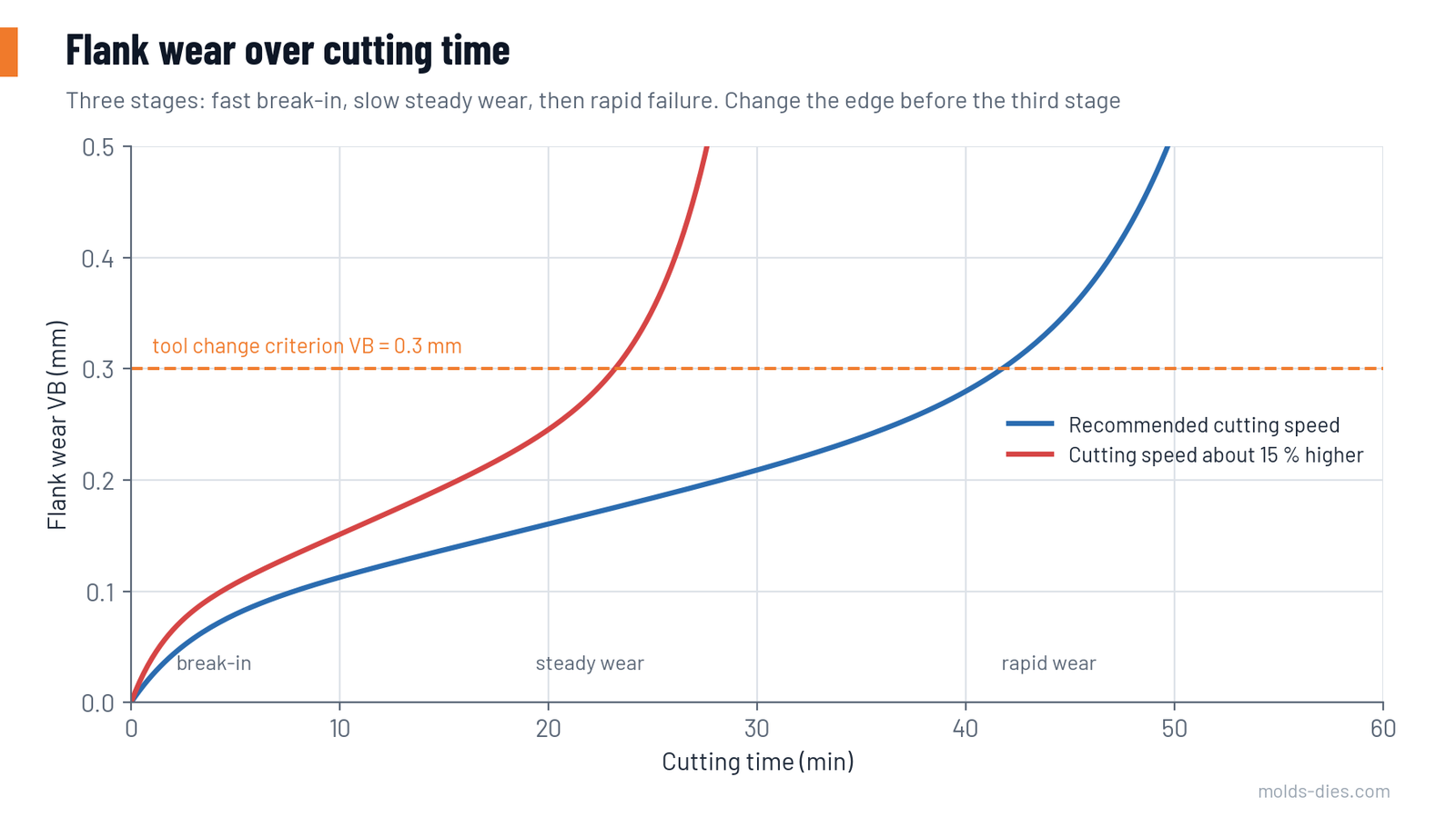
Flank wear follows three stages: a quick initial break-in, a long period of slow steady wear, and a final stage where wear accelerates until the edge fails. The edge should be changed near the end of the second stage.
| Operation | Usual flank wear limit VB (mm) |
|---|---|
| Finishing | 0.1–0.2 |
| General machining | 0.3 |
| Roughing | 0.4–0.6 |
In practice the limit is often reached first by a symptom: surface finish out of tolerance, dimension drifting, burrs, noise or rising spindle load. Convert the limit into a number the operator can use: parts per edge or minutes in cut.
Speed has the strongest effect on tool life. As a rule for carbide tools, raising the cutting speed by 15 % cuts tool life roughly in half, and lowering it by 15 % roughly doubles it. Feed has a smaller effect and depth of cut the smallest. So to remove more metal per edge, increase depth first, then feed, and speed last.
A routine for the shop
- Keep worn edges from each job in a labelled tray for a week instead of scrapping them.
- Inspect with a loupe and classify the dominant pattern.
- Record material, grade, speed, feed, depth, coolant and edge life.
- Change one parameter according to the tables and compare the next edge.
- Fix the proven values and the edge life on the setup sheet.
When different edges on the same job show different patterns, look at stability and run-out first. Consistent wear is the sign of a controlled process; inconsistent wear means something is moving.
Common mistakes
| Mistake | Result |
|---|---|
| Lowering speed to cure built-up edge | It gets worse |
| Choosing a harder grade when the edge chips | More chipping |
| Running every edge to breakage | Damaged workpieces and holders; cause unknown |
| Intermittent coolant in milling | Thermal cracks |
| Same depth of cut on every pass in stainless | Notch wear |
Key takeaways
- Even flank wear is the target. Every other pattern points to a specific correction.
- Crater wear and fast flank wear mean too much heat: lower the speed. Built-up edge means too little: raise it.
- Chipping and thermal cracks need a tougher grade and a more stable, consistent cut.
- Change edges by a defined limit and examine them; speed affects tool life more than feed or depth.
Related Articles
Trochoidal Milling and Chip Thinning in Tool Steel
How trochoidal (dynamic) milling works, how to compensate for radial chip thinning, and starting parameters for roughing tool steel.
Wire EDM: Number of Passes, Surface Finish and Accuracy
How rough cut and skim cuts determine wire EDM accuracy and surface finish, with typical values for passes, offsets, corner radius and recast layer.
Hard Milling vs. EDM for Mold Cavities: When to Use Each
A decision guide for finishing hardened mold and die cavities: when hard milling is faster and better, and when sinker EDM is still required.
Milling Speeds and Feeds: How to Calculate and Adjust
The formulas for spindle speed, table feed and metal removal rate in milling, starting values by material, and how to adjust them at the machine.
Types of Chips: Understanding Their Meaning for Optimal Machining
Learn about the different types of chips formed during machining processes and how understanding chip formation can optimize your manufacturing operations
Climb Milling vs Conventional Milling: A Comparative Analysis and Application Recommendations
Compare climb and conventional milling techniques to improve machining surface finish, accuracy, and tool wear management. Learn the best applications for each method