
Trochoidal Milling and Chip Thinning in Tool Steel
-
 Mohamed Aboelfotouh
- Sector : Machining
- Oct. 2, 2026, 6:41 p.m.
Conventional roughing of tool steel uses a wide radial cut and a shallow depth. Only the bottom few millimetres of the cutter do the work, they do it under high load and heat, and the tool is worn out while most of its flute length is still new. Trochoidal milling, also sold as dynamic or high-efficiency milling, turns this around: a small radial cut, the full flute length, and a tool path that keeps the engagement constant. This article explains how it works, how to correct the feed for chip thinning, and where to start in tool steel.
The idea
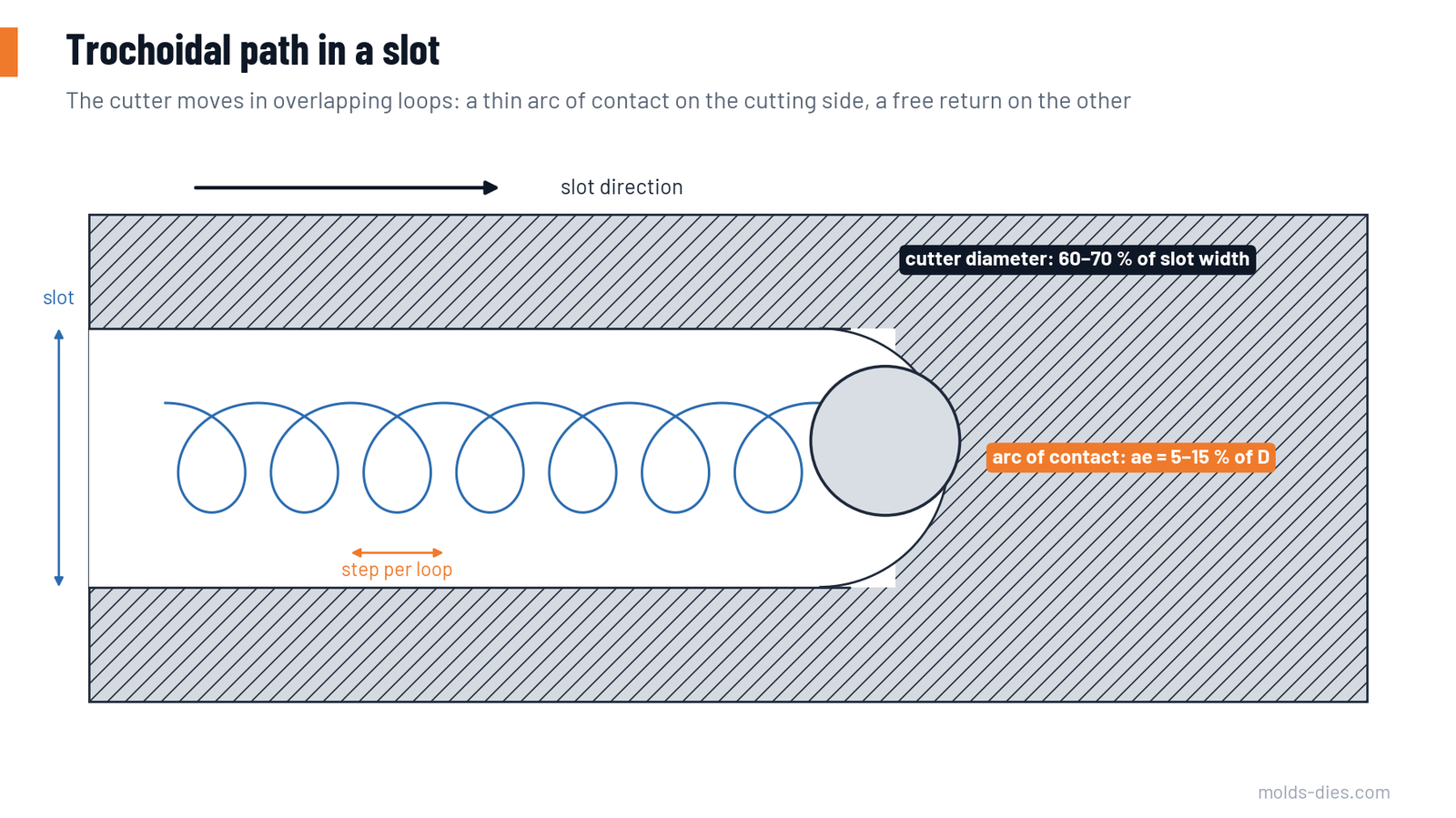
In a full slot, the cutter is engaged over 180°. Each tooth spends half of every revolution in the cut, heat builds up, and the chip has nowhere to go. In a trochoidal path, the cutter is smaller than the slot and moves in a series of overlapping loops. It cuts along a thin arc on the forward side of each loop and returns through the open space behind.
The same principle is applied to pockets and open shoulders by CAM software: the path is shaped so the radial engagement never exceeds a set value, even in corners.
| Conventional slotting or roughing | Trochoidal or constant-engagement roughing | |
|---|---|---|
| Radial engagement ae | 50–100 % of the diameter | 5–15 % of the diameter |
| Axial depth ap | 0.5–1 × D | 2 × D or the full flute length |
| Engagement angle | Up to 180° | About 25–45° |
| Heat | Concentrated at the tool tip | Spread over the flute; short contact time per tooth |
| Radial force | High and varying, peaks in corners | Low and constant |
| Tool wear | At the tip only | Even along the flute |
| Path length | Short | Long; needs high feed to pay off |
Chip thinning
With a small radial engagement, each tooth enters and leaves the material before it reaches the widest part of its arc. The thickest part of the chip is therefore thinner than the programmed feed per tooth.
- Maximum chip thickness = fz × 2 × √(r × (1 − r)), where r = ae ÷ D (valid for r below 0.5)
To keep the chip at the thickness the cutting edge needs, the feed per tooth must be multiplied by the inverse of that factor.
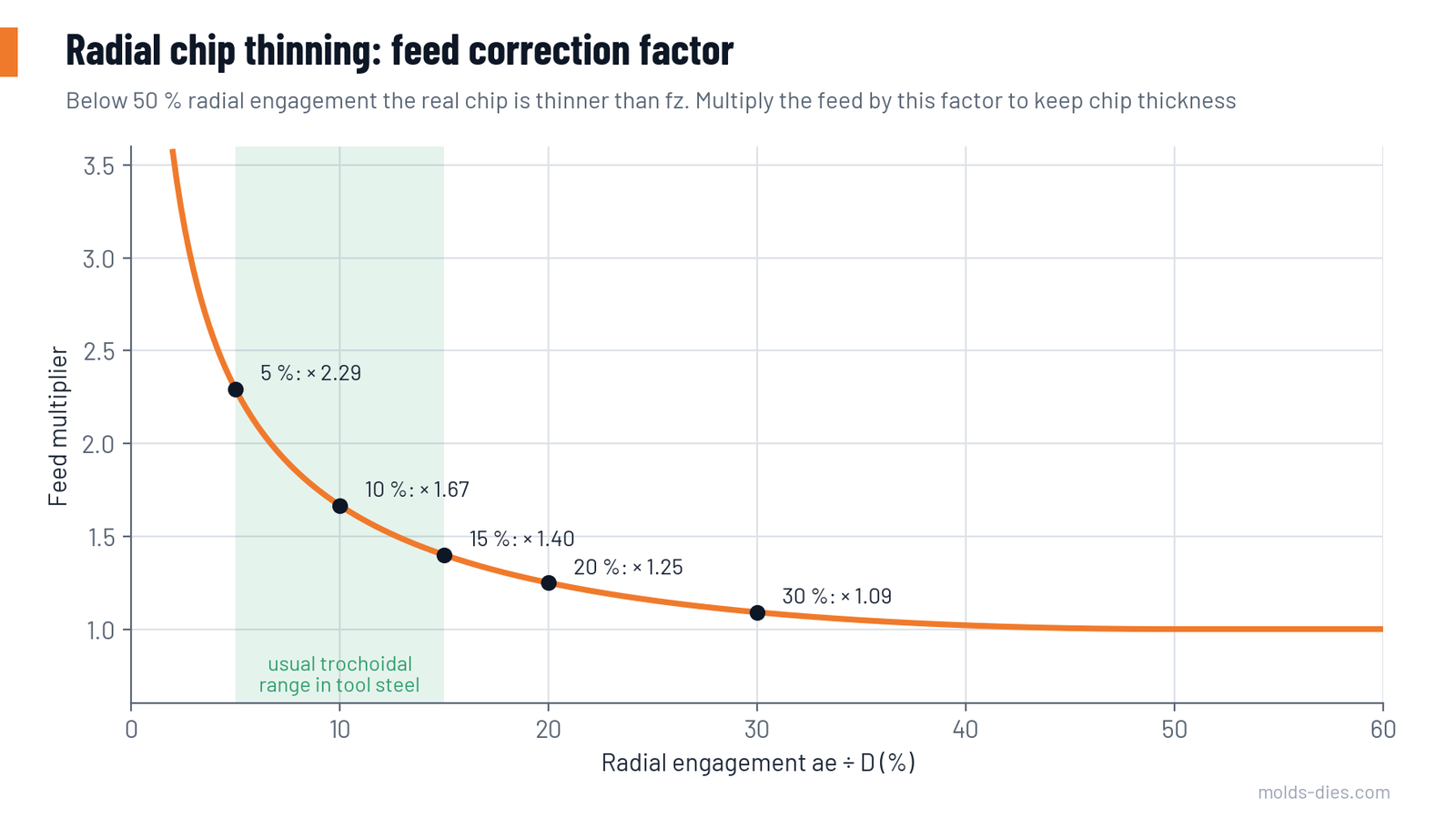
| Radial engagement ae ÷ D | Chip thickness as a share of fz | Feed multiplier |
|---|---|---|
| 50 % or more | 100 % | 1.00 |
| 30 % | 92 % | 1.09 |
| 20 % | 80 % | 1.25 |
| 15 % | 71 % | 1.40 |
| 10 % | 60 % | 1.67 |
| 5 % | 44 % | 2.29 |
If the feed is not corrected, the chip becomes so thin that the edge rubs instead of cutting. The symptoms are heat, a glazed surface, squealing and rapid flank wear, which is the opposite of what the strategy promises.
Because each tooth is in contact for only a short arc, the cutting speed can usually be raised as well, often by 30–100 % compared with slotting values for the same material.
Starting parameters for tool steel
For coated solid-carbide end mills with five or more flutes, 10–12 mm diameter. "Target chip thickness" is the value after correction for chip thinning.
| Material condition | ae (% of D) | ap | Vc (m/min) | Target chip thickness (mm) |
|---|---|---|---|---|
| Annealed tool steel (H13, D2, P20 soft) | 10–15 | 2 × D | 150–220 | 0.05–0.08 |
| Pre-hardened, 30–40 HRC | 8–12 | 2 × D | 120–180 | 0.04–0.07 |
| Hardened, 45–55 HRC | 5–8 | 1–1.5 × D | 80–140 | 0.03–0.05 |
| Hardened, above 55 HRC | 3–5 | 1 × D | 60–100 | 0.02–0.04 |
Start at the lower end, listen to the cut and look at the chips, then increase the feed before the speed.
Worked example
Roughing a pocket in pre-hardened mold steel at 35 HRC with a 10 mm, five-flute end mill.
| Quantity | Calculation | Result |
|---|---|---|
| Radial engagement | 10 % of 10 mm | 1.0 mm |
| Axial depth | 2 × D | 20 mm |
| Cutting speed | chosen | 160 m/min |
| Spindle speed | 1000 × 160 ÷ (3.14 × 10) | 5,093 rev/min |
| Target chip thickness | chosen | 0.05 mm |
| Feed per tooth | 0.05 × 1.67 | 0.083 mm |
| Table feed | 5,093 × 5 × 0.083 | 2,114 mm/min |
| Removal rate while cutting | 1.0 × 20 × 2,114 ÷ 1000 | 42 cm³/min |
For comparison, conventional roughing with the same tool at ae = 5 mm, ap = 5 mm, 110 m/min and 0.05 mm per tooth gives a table feed of about 700 mm/min with four flutes and a removal rate of about 18 cm³/min, with all the wear on the bottom 5 mm of the tool.
Two cautions about the comparison. In a closed slot, part of every loop is a return move in air, so the average removal rate is roughly half the cutting value. And the benefit depends on the machine reaching the programmed feed in short, curved moves.
What the method needs
| Element | Requirement | Why |
|---|---|---|
| CAM software | Tool paths with controlled engagement angle and smooth, tangential moves | Hand-programmed circles do not keep the engagement constant in corners |
| Machine | Good acceleration and look-ahead; enough spindle speed | The feed must actually be reached on short arcs |
| Tool | Five to seven flutes or more, variable pitch, small corner radius, chip splitters for long cuts | Low ae leaves room for more flutes; splitters break long chips |
| Holder | Shrink-fit, hydraulic or side-lock with pull-out protection; low run-out | Long axial cuts create a strong pull-out force along the helix |
| Chip removal | Strong air blast, or through-tool air, in steel; flood coolant in stainless and heat-resistant alloys | Re-cut chips chip the edge; thermal shock from intermittent coolant cracks carbide |
| Workpiece clamping | Rigid over the whole height | Side force acts over a long flute length |
Slots
| Parameter | Guideline |
|---|---|
| Cutter diameter | About 60–70 % of the slot width |
| Step per loop | Chosen so the maximum radial engagement stays at 5–15 % of D |
| Depth | Full slot depth in one pass, up to the flute length |
| Entry | Helical or ramp entry, or from an open end |
Slots deeper than twice their width, which are difficult by conventional slotting, are where trochoidal milling shows the largest gain in tool life.
Checking the cut
| Observation | Meaning | Action |
|---|---|---|
| Even, quiet sound; short, straw to light-blue chips in steel | Heat is leaving with the chip | Increase feed in steps |
| Squeal, glazed wall | Chip too thin | Increase feed per tooth |
| Dark blue or purple chips, sparks | Too much heat | Reduce cutting speed or ae |
| Loud knocks in corners | Engagement rising in corners | Check the CAM minimum-radius and engagement settings |
| Wear only on a band near the tip | ap too small | Use more of the flute length |
| Tool pulled out of the holder | Holder grip too low | Use pull-out protection |
| Tapered wall | Deflection over a long flute | Reduce ae; leave stock for a finishing pass |
Where it does not pay
- Shallow features, where the depth is less than about one diameter: there is no flute length to exploit.
- Thin, flexible walls that cannot take side force over their full height.
- Machines with slow acceleration, where the programmed feed is never reached.
- Very soft, sticky materials at low speeds, where the thin chip smears.
Common mistakes
| Mistake | Result |
|---|---|
| Small radial engagement with the slotting feed per tooth | Rubbing, heat, short tool life |
| Raising ae to "save time" | Engagement angle and heat rise sharply; the tool fails |
| Four-flute tool at slotting speed | Low removal rate; no gain over conventional roughing |
| Flood coolant in hardened steel | Thermal cracking of the edges |
| Programming simple circles by hand in pockets | Engagement peaks in corners |
| Ordinary collet chuck with a 2 × D axial cut | Tool creeps out and gouges the floor |
Key takeaways
- Trochoidal milling uses a small radial engagement, the full flute length and a constant engagement angle.
- Correct the feed for chip thinning: at 10 % engagement multiply the feed per tooth by about 1.7, at 5 % by about 2.3.
- In tool steel start at 5–15 % radial engagement and up to 2 × D depth, with multi-flute tools, secure holders and air blast.
- The gain is longest in deep slots and deep pockets, and depends on CAM and machine dynamics.
Related Articles
Reading Tool Wear: Flank, Crater, Notch and Built-Up Edge
How to recognize the main cutting tool wear patterns — flank, crater, notch, built-up edge, chipping and thermal cracks — and the correction for each.
Wire EDM: Number of Passes, Surface Finish and Accuracy
How rough cut and skim cuts determine wire EDM accuracy and surface finish, with typical values for passes, offsets, corner radius and recast layer.
Hard Milling vs. EDM for Mold Cavities: When to Use Each
A decision guide for finishing hardened mold and die cavities: when hard milling is faster and better, and when sinker EDM is still required.
Milling Speeds and Feeds: How to Calculate and Adjust
The formulas for spindle speed, table feed and metal removal rate in milling, starting values by material, and how to adjust them at the machine.
Types of Chips: Understanding Their Meaning for Optimal Machining
Learn about the different types of chips formed during machining processes and how understanding chip formation can optimize your manufacturing operations
Climb Milling vs Conventional Milling: A Comparative Analysis and Application Recommendations
Compare climb and conventional milling techniques to improve machining surface finish, accuracy, and tool wear management. Learn the best applications for each method