
Milling Speeds and Feeds: How to Calculate and Adjust
-
 Mohamed Aboelfotouh
- Sector : Machining
- Oct. 2, 2026, 6:39 p.m.
Every milling operation is defined by a small set of numbers: cutting speed, feed per tooth, and the width and depth of cut. Catalogues give recommended values, but the machine needs spindle speed and table feed, and the catalogue values assume a short, rigid setup that the shop floor does not always have. This article gives the formulas, a table of starting values for common mold and die materials, and a guide to adjusting them when the cut does not behave.
The parameters
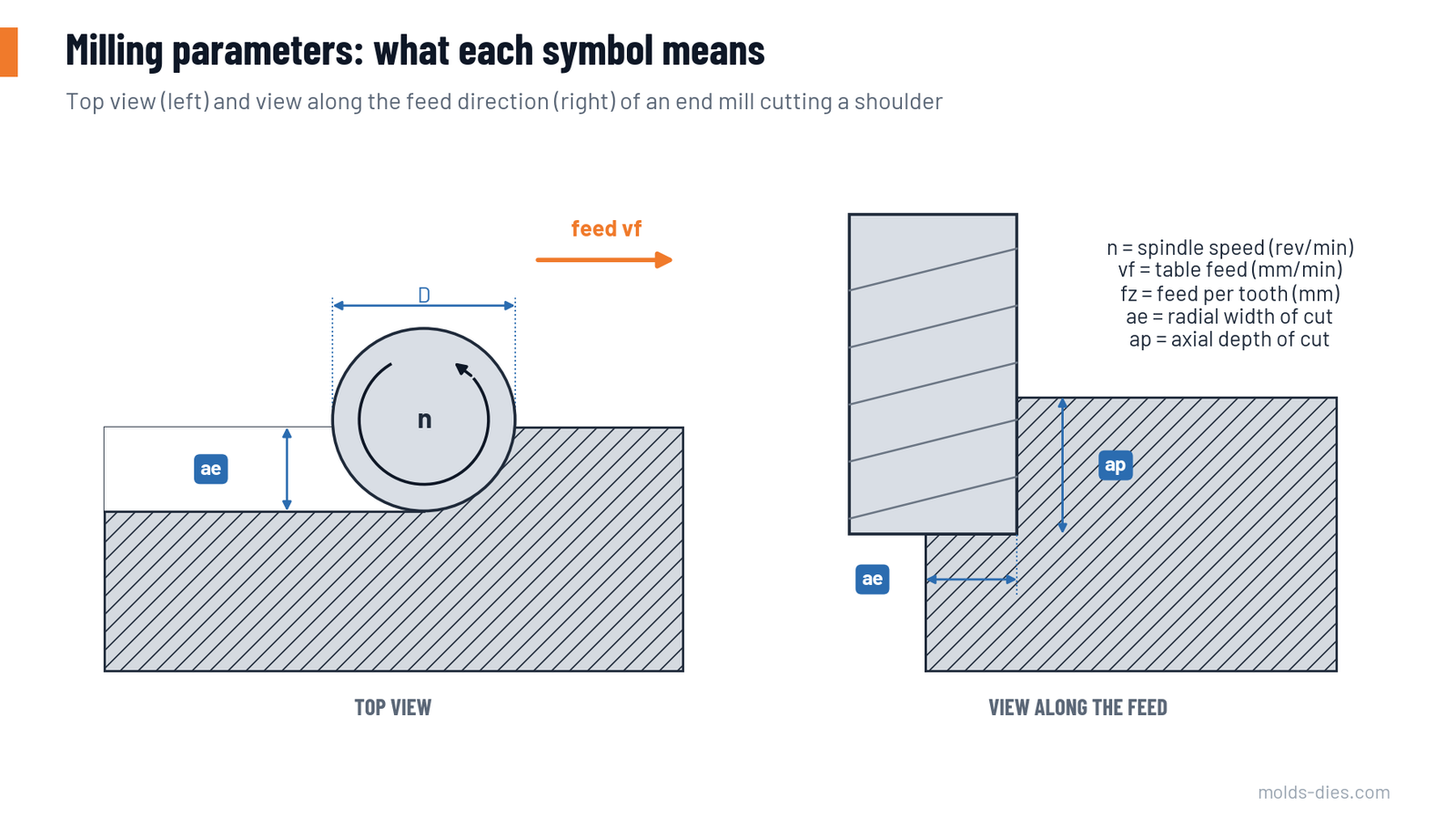
| Symbol | Name | Unit | Set by |
|---|---|---|---|
| Vc | Cutting speed: the speed of the cutting edge through the material | m/min | Tool material, coating and workpiece material |
| n | Spindle speed | rev/min | Calculated from Vc and D |
| fz | Feed per tooth: how far the tool advances for each cutting edge | mm | Tool diameter, workpiece material, finish required |
| z | Number of teeth (flutes) | — | The tool |
| vf | Table feed | mm/min | Calculated from n, z and fz |
| ae | Radial width of cut | mm | Strategy |
| ap | Axial depth of cut | mm | Strategy |
| Q | Metal removal rate | cm³/min | Result |
The four formulas
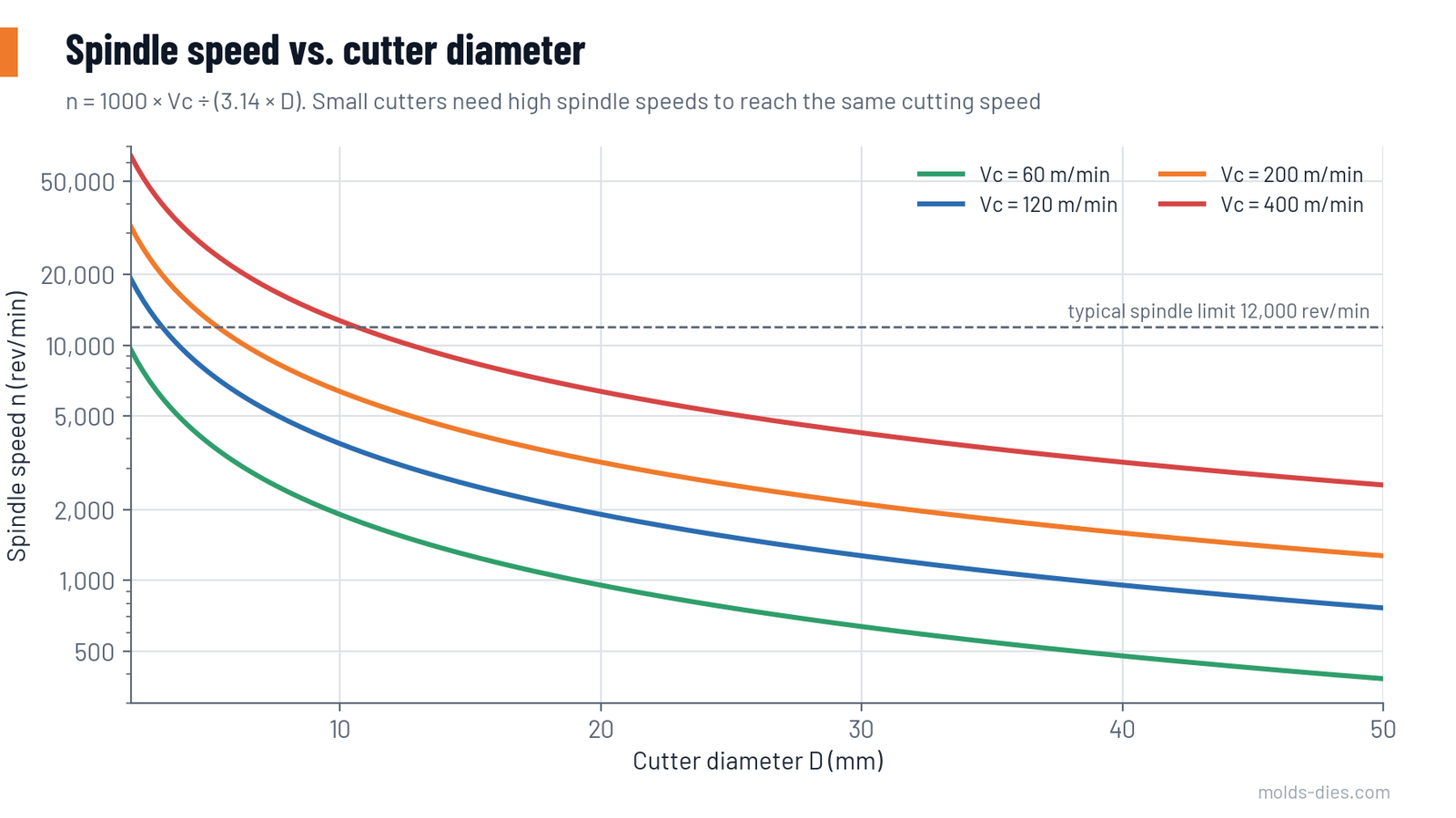
- Spindle speed: n = (1000 × Vc) ÷ (3.14 × D)
- Table feed: vf = n × z × fz
- Metal removal rate: Q = (ae × ap × vf) ÷ 1000
- Spindle power: P ≈ (ae × ap × vf × kc) ÷ (60,000,000 × 0.8) in kW
In the last formula, kc is the specific cutting force of the material in N/mm², and 0.8 is a typical machine efficiency.
Starting values
For coated solid-carbide end mills, side milling with a radial width of 30–50 % of the diameter. Feed per tooth is given for a 10 mm cutter.
| Material | Vc (m/min) | fz for D = 10 mm (mm) | kc (N/mm²) |
|---|---|---|---|
| Aluminum alloys | 300–800 | 0.06–0.15 | 500–800 |
| Copper (electrodes) | 150–300 | 0.04–0.08 | 1,000–1,400 |
| Graphite (electrodes) | 300–600 | 0.05–0.10 | — |
| Cast iron | 120–200 | 0.05–0.10 | 1,000–1,300 |
| Low-carbon steel | 150–250 | 0.05–0.10 | 1,500–1,800 |
| Pre-hardened mold steel, about 30 HRC | 120–180 | 0.04–0.08 | 1,800–2,200 |
| Tool steel, annealed (H13, D2) | 100–160 | 0.04–0.08 | 1,900–2,400 |
| Stainless steel | 80–140 | 0.04–0.08 | 1,800–2,400 |
| Hardened steel, 45–52 HRC | 80–140 | 0.03–0.06 | 2,500–3,500 |
| Hardened steel, 55–62 HRC | 50–100 | 0.02–0.05 | 3,500–4,500 |
Scaling feed per tooth with diameter. For steels, fz is roughly 0.5–1 % of the cutter diameter:
| Cutter diameter (mm) | fz in steel (mm) |
|---|---|
| 3 | 0.015–0.03 |
| 6 | 0.03–0.05 |
| 10 | 0.05–0.08 |
| 16 | 0.08–0.12 |
| 20 | 0.10–0.15 |
Always start from the tool maker's data for the specific tool when it is available. Use the tables when it is not, and begin at the lower end.
Worked example
Side milling pre-hardened mold steel (30 HRC) with a 10 mm, four-flute coated carbide end mill. Radial width 3 mm, axial depth 10 mm.
| Quantity | Calculation | Result |
|---|---|---|
| Cutting speed | chosen | 150 m/min |
| Spindle speed | 1000 × 150 ÷ (3.14 × 10) | 4,775 rev/min |
| Feed per tooth | chosen | 0.06 mm |
| Table feed | 4,775 × 4 × 0.06 | 1,146 mm/min |
| Removal rate | 3 × 10 × 1,146 ÷ 1000 | 34 cm³/min |
| Power, kc = 2,000 | 3 × 10 × 1,146 × 2,000 ÷ 48,000,000 | 1.4 kW |
The Milling Cutting Conditions Calculator on this site runs the same calculation.
Three corrections the basic formulas miss
1. Effective diameter of ball-nose cutters. A ball-nose cutter working at a small depth cuts on a much smaller diameter than its nominal size.
- Effective diameter = 2 × √(ap × (D − ap))
A 10 mm ball at 0.3 mm depth cuts at 3.4 mm diameter. To reach 150 m/min it needs about 14,000 rev/min, not 4,775. If the spindle speed is calculated from the nominal diameter, the tool rubs at one third of the intended speed and finish and tool life suffer. Tilting the tool or the surface so the tip is not cutting also helps: the centre of a ball has zero cutting speed.
2. Chip thinning at small radial widths. When ae is below half the diameter, the actual chip is thinner than fz. At 10 % engagement, the chip is only 60 % of fz. Increase the feed per tooth to compensate, or the edge rubs instead of cutting.
3. Spindle speed limit. When the calculated speed is above what the spindle can reach, run at maximum speed and calculate the table feed from the real speed with the normal fz. Do not keep the table feed that belonged to the higher speed: that overloads each tooth.
Choosing ae and ap
| Operation | Radial width ae | Axial depth ap |
|---|---|---|
| Full slot | 100 % of D | Up to 0.5–1 × D in steel |
| Conventional roughing, side milling | 30–50 % of D | 1–1.5 × D |
| High-efficiency roughing | 5–15 % of D | 2 × D or more, with feed corrected for chip thinning |
| Finishing walls | 0.1–0.5 mm | Full wall height if the tool is stiff enough, otherwise in steps |
| Finishing 3D surfaces with a ball | Step-over from the required scallop height | 0.1–0.3 mm stock |
Adjusting at the machine
Change one parameter at a time and note the result.
| Symptom | Likely cause | First adjustment |
|---|---|---|
| Chatter, wavy surface | Tool stick-out too long, engagement too large, speed at a resonance | Shorten the stick-out; reduce ae or ap; change spindle speed by 10–15 % up or down |
| Rapid flank wear | Cutting speed too high | Reduce Vc by 15–20 % |
| Built-up edge, torn surface | Speed too low, edge not sharp enough | Increase Vc; use a sharper geometry or a different coating |
| Edge chipping | Feed too high for the edge, vibration, re-cutting chips | Reduce fz; improve chip evacuation; check run-out |
| Squealing, glazed surface, heat | Feed too low: the edge rubs | Increase fz |
| Tool deflection, tapered wall | Radial force too high for the tool length | Reduce ae; add a spring pass; use a shorter or larger tool |
| Chips blue or welded in steel | Heat staying in the cut | Check coolant or air blast; reduce Vc |
| Poor finish at the bottom of a wall | Run-out or worn corner | Check the holder; index or replace the tool |
Two general rules:
- Stick-out matters more than anything else. Deflection grows with the cube of the unsupported length. A tool hanging out 5 × D deflects about eight times as much as one at 2.5 × D under the same force. For long reach, reduce ae and fz, not only speed.
- Run-out shortens tool life quickly. With 0.02 mm run-out and a feed of 0.04 mm per tooth, one tooth takes most of the load. Use good holders and check run-out on small tools.
Climb or conventional
Use climb milling as the default on CNC machines with ball screws: the chip starts thick and ends thin, heat goes into the chip, and the surface is better. Use conventional milling for hard skin, scale or flame-cut edges, and on machines with backlash.
Common mistakes
| Mistake | Result |
|---|---|
| Table feed copied from another tool diameter | Wrong chip load |
| Reducing feed when the tool wears fast | Rubbing; wear gets worse. Reduce speed instead |
| Nominal diameter used for ball-nose finishing | Low real cutting speed, poor finish |
| Same parameters for a 3 × D and a 6 × D stick-out | Chatter and breakage |
| Ignoring chip thinning in light radial cuts | Short tool life from rubbing |
| No record of what worked | Every job starts from zero |
Key takeaways
- Spindle speed comes from cutting speed and diameter; table feed comes from spindle speed, number of teeth and feed per tooth.
- Start from the tool maker's data or the lower end of the table, then adjust one parameter at a time.
- Correct for the effective diameter of ball-nose cutters and for chip thinning in light radial cuts.
- When wear is too fast, lower the speed. When the tool rubs or squeals, raise the feed. When it chatters, shorten the tool or reduce engagement.
Related Articles
Trochoidal Milling and Chip Thinning in Tool Steel
How trochoidal (dynamic) milling works, how to compensate for radial chip thinning, and starting parameters for roughing tool steel.
Reading Tool Wear: Flank, Crater, Notch and Built-Up Edge
How to recognize the main cutting tool wear patterns — flank, crater, notch, built-up edge, chipping and thermal cracks — and the correction for each.
Wire EDM: Number of Passes, Surface Finish and Accuracy
How rough cut and skim cuts determine wire EDM accuracy and surface finish, with typical values for passes, offsets, corner radius and recast layer.
Hard Milling vs. EDM for Mold Cavities: When to Use Each
A decision guide for finishing hardened mold and die cavities: when hard milling is faster and better, and when sinker EDM is still required.
Types of Chips: Understanding Their Meaning for Optimal Machining
Learn about the different types of chips formed during machining processes and how understanding chip formation can optimize your manufacturing operations
Climb Milling vs Conventional Milling: A Comparative Analysis and Application Recommendations
Compare climb and conventional milling techniques to improve machining surface finish, accuracy, and tool wear management. Learn the best applications for each method