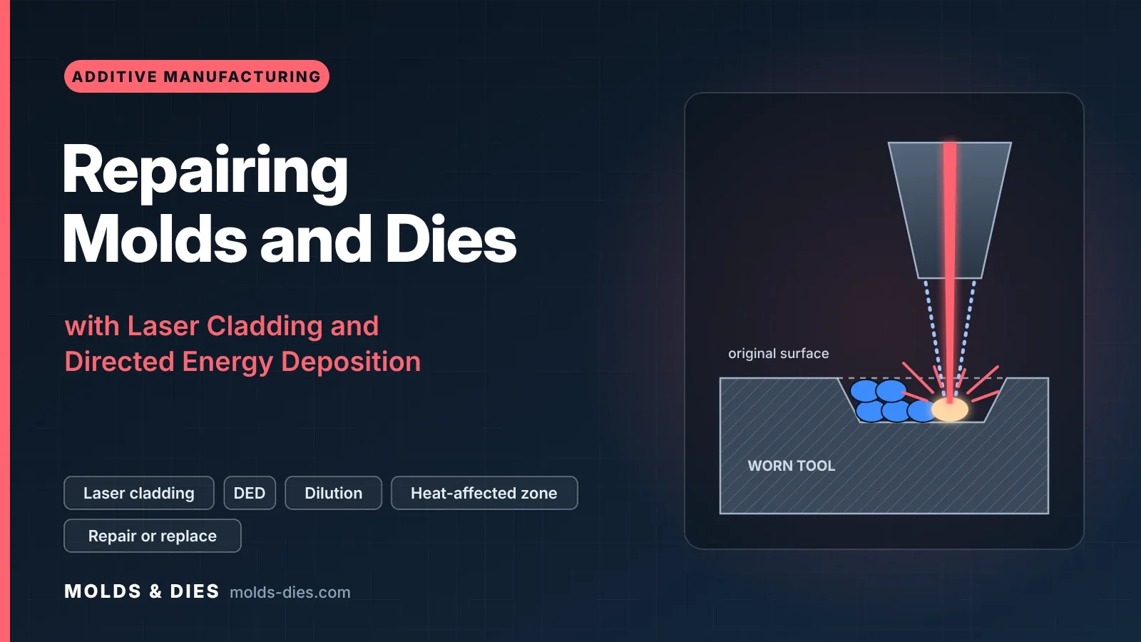
Repairing Molds and Dies with Laser Cladding and Directed Energy Deposition
-
 Mohamed Aboelfotouh
- Sector : Additive Manufacturing
- Oct. 9, 2026, 6:17 a.m.
A worn parting edge, a cracked die casting insert or a late engineering change does not always need a new insert. Material can be added to the existing steel and machined back to size. The method used to add it decides how much heat enters the tool, and heat is what causes distortion, soft zones and new cracks. This article compares the repair methods, explains laser cladding and directed energy deposition (DED), and gives a repair procedure and a rule for deciding between repair and replacement.
The repair methods
| Property | TIG welding | Manual pulsed laser welding | Laser cladding / DED |
|---|---|---|---|
| Filler | Rod, 1–2.4 mm | Wire, 0.2–0.6 mm | Powder or wire, fed automatically |
| Heat input | High | Very low | Low |
| Heat-affected zone | 2–5 mm | 0.05–0.3 mm | 0.3–1 mm |
| Preheating of tool steel | Required | Usually not needed for small repairs | Often not needed; used on crack-sensitive steels |
| Deposit rate | High | Very low, grams per hour | Medium to high, 0.2–1.5 kg/h |
| Control | Manual | Manual, under a microscope | CNC or robot, path from CAD |
| Distortion | Noticeable | Negligible | Small |
| Best for | Large volumes in non-critical areas | Edges, parting lines, small defects, polished surfaces | Worn areas, rebuilt edges, design changes, hardfacing |
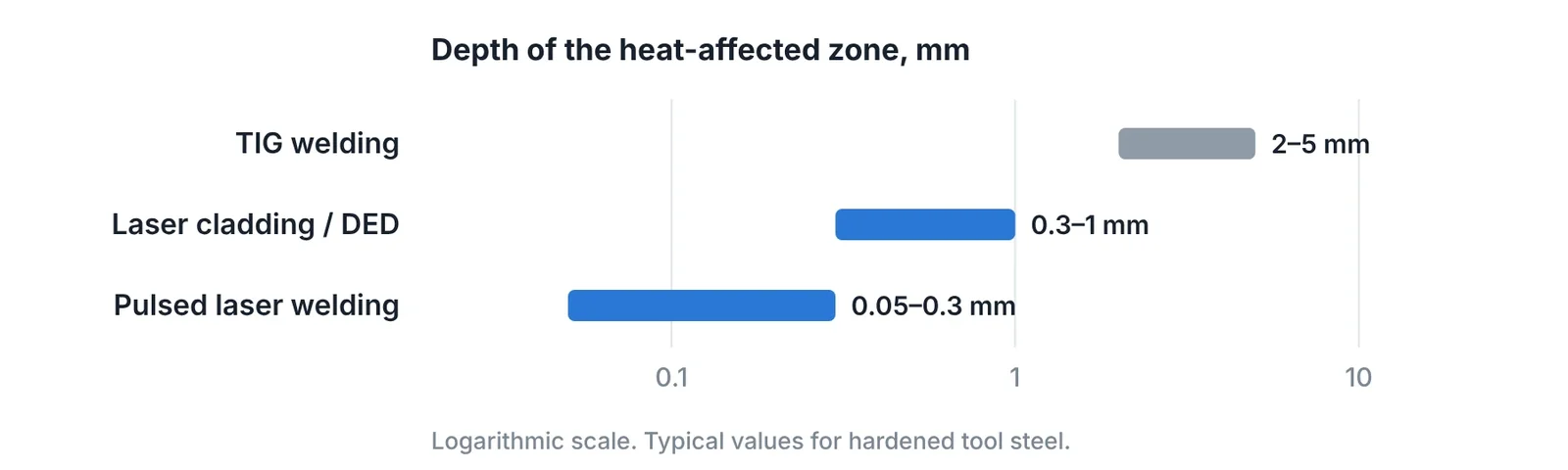
The heat-affected zone matters because it is the part of the original tool that changes. In hardened steel, one band of it is re-hardened and brittle and the next band is over-tempered and soft. On a polished or textured cavity the soft band shows as a visible ring around the repair. On a die casting insert it is where the next heat check starts.
How laser cladding works
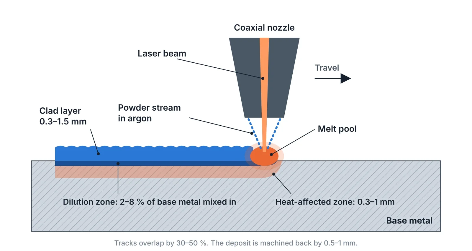
A laser beam creates a small melt pool on the surface of the tool. A nozzle around the beam feeds metal powder into the pool in a stream of argon, which also shields the pool from air. As the head moves, the pool solidifies into a bead that is fused to the base metal. Beads are laid side by side with an overlap of 30–50 % to form a layer, and layers are stacked to build height.
| Parameter | Typical range | Effect |
|---|---|---|
| Bead width | 1–5 mm | Set by the laser spot size |
| Layer height | 0.3–1.5 mm | Set by powder feed and travel speed |
| Dilution | 2–8 % | Share of base metal mixed into the deposit |
| Track overlap | 30–50 % | Too little leaves valleys and lack of fusion |
| Machining stock on the deposit | 0.5–1 mm | The surface of the deposit is wavy |
Dilution is the key quality measure. Too little and the bead is not fused to the base. Too much and the deposit takes on the composition of the base metal and loses its intended hardness. A low, stable dilution is what separates laser cladding from arc welding, where 20–30 % is normal.
DED is the same process used to build volume instead of a surface layer. On a five-axis machine or a robot it rebuilds a broken corner, adds a rib or boss for a design change, or deposits a wear-resistant alloy on a tool made from a tougher, cheaper steel.
Repair procedure
- Identify the steel, its hardness and the cause. A repair that does not remove the cause fails the same way. Wear, heat checking, overload and a design weakness call for different actions.
- Remove all damaged material. Machine or grind back to sound metal. For cracks, check with dye penetrant that the whole crack is gone. A crack left under the deposit continues to grow.
- Shape the groove for access. Open the side walls to at least 30° from vertical and round the bottom so the nozzle and the powder stream reach every surface.
- Remove surface layers. Machine off nitrided layers, coatings and plating in and around the repair zone. Nitrogen in the melt pool causes porosity and cracking.
- Clean and degrease. Die lubricant, oil and oxide cause pores.
- Choose the filler from the table below.
- Preheat if required. For TIG welding, typical values are 200–300 °C for pre-hardened mold steel and 320–400 °C for H13, held during welding and followed by slow cooling.
- Deposit with 0.5–1 mm of overbuild on every face to be machined.
- Temper or stress relieve. Use a temperature 25–30 °C below the last tempering temperature of the tool so that the base hardness is kept.
- Machine, EDM and polish to size.
- Inspect. Check dimensions, hardness of the deposit and the adjacent zone, and repeat the penetrant test.
- Restore the surface treatment and record the repair in the tool history.
Choosing the filler
| Tool and damage | Filler | Reason |
|---|---|---|
| Plastic mold, pre-hardened steel, polished or textured cavity | Matching composition and hardness | The repair must polish and etch like the base |
| Plastic mold, worn parting line or gate | Matching or slightly harder tool steel | Wear resistance at the edge |
| HPDC insert in H13, cracked or washed-out area | H13-type or maraging-type filler | Maraging filler is tough as deposited and hardens by ageing without preheat |
| Trim die or cutting edge in cold-work steel | Tough buffer layer, then a hard tool-steel or cobalt-alloy cap | The buffer stops cracks; the cap cuts |
| Forging or hot-forming die | Cobalt- or nickel-based alloy | Keeps hardness at temperature |
| Abrasive wear surface | Nickel alloy with tungsten carbide | Highest abrasion resistance; machined by grinding |
Hard fillers crack on a hard, cold base. A soft buffer layer under a hard cap is the standard answer for cutting edges. Steel selection for the base tool is covered in Punch and Die Steels: Grade, Hardness and Coating by Application.
Design changes instead of new inserts
Removing steel for a design change is easy. Adding steel used to mean a new insert or a large weld. With DED the added volume is deposited where the change is needed and machined to the new shape.
- Suitable changes: a moved rib, a closed pocket, a relocated boss, a raised shut-off, a longer core.
- Deposit only on the area affected, with the path programmed from the difference between the old and the new CAD models.
- On textured or polished cavity surfaces, use a matching filler and expect to re-texture the surrounding area.
- Typical lead time is days, against weeks for a new insert.
Repair or replace
| Condition | Decision |
|---|---|
| Local damage, sound steel around it, cause understood | Repair |
| Repair cost below about one third of a new insert and lead time shorter | Repair |
| Design change affecting a small area | Repair by deposition |
| Heat-check network over the whole cavity of a die casting insert | Replace; the steel is fatigued everywhere |
| Third repair in the same place | Replace or redesign; the cause has not been removed |
| Crack reaching a cooling channel | Replace in most cases |
| Optical surface | Replace, or pulsed laser welding by a specialist |
The cost side of this decision uses the same hour and material estimate as a new tool, described in How to Estimate the Cost of a Mold or Die. Planned inspection finds damage while it is still small and cheap to repair. See the preventive maintenance program and, for die casting, Die Life in HPDC.
Common mistakes
| Mistake | Result | Correct approach |
|---|---|---|
| Depositing over a crack | Crack returns through the repair | Machine out and confirm with penetrant |
| Cladding on a nitrided surface | Porosity and cracks at the fusion line | Remove the nitrided layer first |
| Hard filler directly on hardened steel | Cracking on cooling | Buffer layer, or preheat |
| TIG welding hardened steel without preheat | Brittle zone, cracks | Preheat, hold, cool slowly, temper |
| Tempering above the original tempering temperature | Whole insert softens | Stay 25–30 °C below it |
| No overbuild | Low spots after machining | 0.5–1 mm stock on the deposit |
| Repairing without finding the cause | Same failure after a short time | Fix the cause with the repair |
Key takeaways
- The quality of a tool repair depends on heat input. Laser methods leave a heat-affected zone about ten times thinner than TIG welding.
- Pulsed laser welding suits small, fine repairs. Laser cladding and DED suit larger areas, rebuilt edges, hardfacing and design changes, with CNC control.
- Remove cracks and nitrided layers completely, choose the filler for the function, overbuild by 0.5–1 mm, and temper below the original tempering temperature.
- Repair local damage with a known cause. Replace inserts with general fatigue, repeated failures or cracks into cooling channels.
Related Articles
Additive Manufacturing for Toolmakers: Processes, Materials and Where Each Fits
The additive manufacturing processes that matter in a tool shop: what each one makes, its accuracy and materials, and which mold and die jobs it suits.
Small Batches: Print the Part, Print the Tool, or Cut the Tool?
Break-even calculation for small batches: 3D printed parts, printed mold inserts, aluminum molds and steel molds, with routes for metal and sheet metal parts.
Printing Tool Steel: Maraging, H13 and What Happens After the Build
Printable tool steels compared, with the full post-processing route: stress relief, age hardening, machining allowance, polishing limits and surface treatment.
3D Printed Mold Inserts for Short-Run Injection Molding
How to design and run 3D printed polymer mold inserts for 10 to 100 molded parts: materials, draft, gates, process settings, insert life and failure modes.
Conformal Cooling in Injection Molds and Die Casting Inserts: Design Rules and Payback
Design rules for conformal cooling channels in printed mold inserts: diameter, pitch, distance to cavity, flow, hybrid inserts, HPDC limits and payback.