Punch and Die Steels: Grade, Hardness and Coating by Application
-
 Mohamed Aboelfotouh
- Sector : Sheet Metal
- Oct. 2, 2026, 6:39 p.m.
Punches and die inserts fail in a small number of ways: they wear, chip, crack, pick up sheet material, or deform. Each failure points to a different property of the tool steel. The usual mistake is to answer every problem with a harder or more expensive steel. A harder steel helps against wear and deformation and makes chipping and cracking worse. This article shows how to choose the grade, hardness and coating from the failure you need to prevent.
Start from the failure mode
| Failure | What you see | Property needed | Direction |
|---|---|---|---|
| Abrasive wear | Rounded cutting edge, growing burr, even wear land | Wear resistance (hard carbides) | Higher-alloy steel, higher hardness, coating |
| Adhesive wear, galling | Sheet material welded to the tool; scoring on parts | Low friction, surface that does not bond to the sheet | Coating, better finish, different tool material |
| Chipping | Small pieces broken from the edge | Toughness | Tougher steel, slightly lower hardness, powder-metallurgy grade |
| Cracking, breakage | Punch or insert splits | Toughness, stress relief | Tougher steel; remove stress raisers; correct heat treatment |
| Plastic deformation | Edge rolled over, punch head mushroomed | Compressive strength | Higher hardness |
Look at the worn tools from the current or a similar die before choosing. A punch that has chipped needs toughness even if the edge next to the chip looks worn.
Wear resistance against toughness
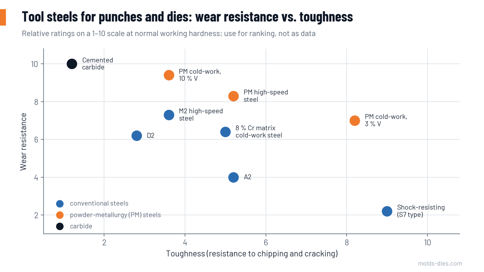
Wear resistance comes mainly from hard carbide particles in the steel. In conventionally cast steels with a high carbide content, such as D2, the carbides are large and arranged in bands, and they act as starting points for cracks. Powder-metallurgy (PM) steels have the same or more carbide in very small, evenly spread particles. That is why PM grades sit toward the upper right of the chart: more wear resistance at equal or better toughness.
The steel families
| Family | Examples | Working hardness (HRC) | Character | Typical use |
|---|---|---|---|---|
| Shock-resisting | S7 type | 54–58 | Very tough, low wear resistance | Heavy blanking of thick plate, punches under bending load, shear blades for thick material |
| Oil- and air-hardening cold-work | O1, A2 | 57–62 | Easy to machine and heat treat; moderate wear resistance | Short and medium runs, form tools, general die parts |
| High-carbon, high-chromium | D2 (1.2379) | 58–62 | High wear resistance, limited toughness | The standard for medium and long runs in mild steel |
| 8 % chromium matrix steels | Modified cold-work grades | 60–62 | Similar wear to D2 with clearly better toughness | Where D2 chips; high-strength sheet |
| High-speed steel | M2 | 60–64 | High hardness and compressive strength, good wear resistance | Small-diameter punches, high stroke rates |
| PM cold-work steels | Grades with about 3 % or 10 % vanadium | 58–64 | Toughest wear-resistant steels (3 % V); extreme wear resistance (10 % V) | Long runs, stainless, high-strength and abrasive sheet |
| PM high-speed steels | — | 62–66 | Very high compressive strength with fair toughness | Fine blanking, thin and hard sheet, small punches |
| Cemented carbide | — | Far above the steel range | Highest wear resistance, brittle | Very long runs in thin sheet, electrical steel laminations |
Selection by sheet material and run length
| Sheet material | Up to about 100,000 parts | 100,000 to 1,000,000 | Over 1,000,000 |
|---|---|---|---|
| Low-carbon steel up to 2 mm | A2 or D2 | D2 | PM cold-work or carbide inserts |
| Low-carbon steel above 3 mm | A2 or shock-resisting | 8 % Cr matrix steel | PM cold-work (3 % V type) |
| Stainless steel | D2 with coating | PM cold-work with coating | PM cold-work or PM high-speed steel with coating |
| High-strength steel (tensile strength above about 600 N/mm²) | 8 % Cr matrix steel | PM cold-work (3 % V type) with coating | PM cold-work with coating; inserts planned for replacement |
| Aluminum | A2 or D2, polished | D2 with a low-friction coating | PM cold-work or carbide, coated |
| Electrical steel, abrasive coated sheet | D2 | PM cold-work (10 % V type) | Carbide |
Read the table as a starting point and move toward toughness (left and down on the chart) when thick or strong sheet, small punches or imperfect press alignment make chipping likely.
Choosing the hardness
Within the range for each grade:
- Upper end for thin sheet, soft sheet and wear-dominated work.
- Lower end for thick sheet, high-strength sheet, slender punches and tools with notches or sharp internal corners.
- A reduction of 2 HRC often stops chipping at a small cost in wear life. Chipped tools must be reground deeply; worn tools need a light regrind. Slightly softer and unchipped is usually the more economical condition.
- The punch and the die do not need the same hardness. Many shops run the die insert 1–2 HRC harder than the punch, since the punch is cheaper to replace.
Coatings and surface treatments
| Treatment | Process temperature | What it gives | Conditions |
|---|---|---|---|
| PVD coatings (TiN, TiCN, TiAlN, AlCrN, CrN) | About 200–500 °C | Hard, low-friction surface 2–5 µm thick; strong against galling and abrasive wear | Steel must have been tempered above the coating temperature, or it softens. Suits D2 tempered at high temperature, high-speed and PM steels. Not suited to steels tempered at about 200 °C |
| Nitriding | About 480–570 °C | Hard case with good sliding properties | Same tempering condition; brittle at sharp cutting edges, better for forming tools |
| CVD and TD (carbide) coatings | About 900–1,050 °C | Very hard, well-bonded layers; excellent against galling in forming and drawing | Tool must be hardened again after coating: distortion; not for tight-tolerance cutting clearances |
| Low-friction carbon coatings (DLC) | Below about 250 °C | Very low friction against aluminum and copper | Thin; needs a hard, well-finished substrate |
A coating is only as good as the surface beneath it. Polish the tool to a fine finish in the direction of sliding before coating, and remove any grinding burn or EDM recast layer.
Heat treatment and finishing rules
- Specify the tempering regime, not only the hardness. D2 tempered two or three times at about 520–540 °C reaches 58–60 HRC with low retained austenite, better dimensional stability and suitability for coating and wire EDM.
- Temper at least twice; high-alloy and PM steels three times.
- After wire or sinker EDM, remove the recast layer by skim cuts or polishing, and stress temper about 25 °C below the last tempering temperature.
- Grind with care. Grinding burn leaves a soft or cracked surface that chips early. Use suitable wheels, coolant and small infeeds.
- Finish cutting edges sharp but not ragged. A light hone on the edge of tools for high-strength sheet reduces chipping.
- Radius every internal corner on punches and inserts; a sharp corner is where cracks start.
Other factors that outweigh steel choice
| Factor | Effect |
|---|---|
| Cutting clearance | Too small a clearance multiplies wear and chipping; larger clearances are used for high-strength and thick sheet |
| Press alignment and die guiding | Misalignment loads one side of the edge and causes chipping that no steel survives |
| Punch length and support | Slender punches need guiding in the stripper |
| Lubrication | Reduces galling and heat, especially in stainless and aluminum |
| Regrind practice | Regrinding before the edge is badly worn removes less material and extends total life |
Common mistakes
| Mistake | Result |
|---|---|
| Raising hardness when the punch chips | More chipping |
| D2 at maximum hardness for thick or high-strength sheet | Edge breaks out |
| PVD coating on low-temperature-tempered steel | Tool softens during coating |
| Coating over a rough or burned surface | Coating flakes off |
| Carbide in a die with poor guiding | Cracked inserts |
| Judging steel cost per kilogram instead of cost per part produced | Cheap steel, expensive downtime |
Key takeaways
- Identify the failure mode first: wear and deformation call for hardness and carbides; chipping and cracking call for toughness.
- D2 at 58–62 HRC is the baseline; 8 % chromium and PM steels give the same or better wear life with more toughness.
- Coatings solve galling and extend wear life, provided the steel was tempered above the coating temperature and the surface is well finished.
- Clearance, alignment and regrind practice often matter more than the grade.
Related Articles
Cutting Force, Stripping Force and Press Tonnage: How to Calculate
Formulas and a worked example for blanking and piercing force, stripping force, the effect of shear angle, and choosing press tonnage.
Deep Drawing: Draw Ratio, Blank Size and Number of Draws
How to calculate blank diameter, draw ratio, number of draws, blank holder force and tool radii for cylindrical deep-drawn parts.
Springback in Bending: Prediction and Compensation
What controls springback in sheet metal bending, how to estimate it from material and R/t ratio, and the die design methods used to compensate for it.
Strip Layout for Progressive Dies: Material Utilization, Pilots and Carriers
How to develop a progressive die strip layout: part orientation, pitch and bridge widths, material utilization, pilot holes, carriers and station sequence.
Sheet Metal Material Selection: HR vs. CR Steel
Compare hot-rolled and cold-rolled steel for sheet metal design. Understand differences in cost, finish, strength, and forming performance to select the right material.
Understanding Press Machines in Sheet Metal Operations
Explore the different types of press machines used in sheet metal manufacturing—manual, hydraulic, pneumatic, eccentric, and press brake—with practical comparisons and engineering insights.
Introduction to Sheet Metal Die Design: Processes, Principles, and Applications
An essential introduction to sheet metal die design, covering key processes like shearing, bending, and forming for efficient manufacturing.