
Deep Drawing: Draw Ratio, Blank Size and Number of Draws
-
 Mohamed Aboelfotouh
- Sector : Sheet Metal
- Oct. 2, 2026, 6:38 p.m.
Deep drawing turns a flat blank into a cup or box by pulling the material through a die with a punch. Whether the part can be made in one draw or needs several, how large the blank must be, and how much force is needed can all be calculated before any tooling is designed. This article gives the calculation sequence for a cylindrical cup, with a worked example, and the tool dimensions that decide between a good part and a torn or wrinkled one.
The tool and its dimensions
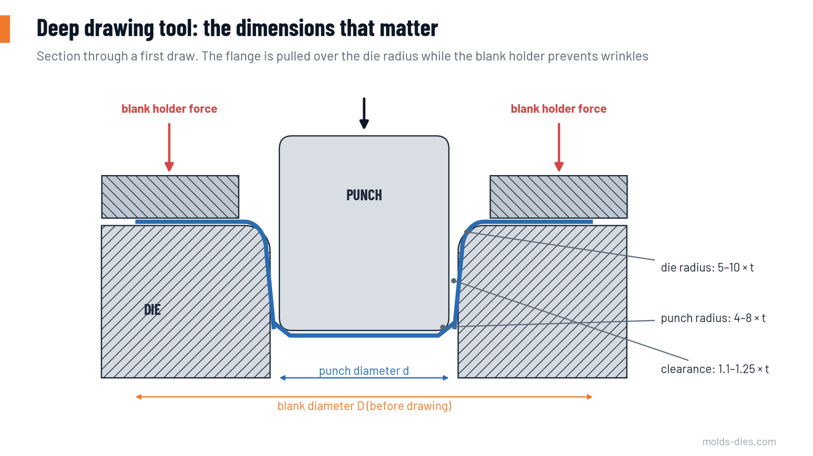
During the draw, the flange of the blank is pulled inward over the die radius. Its circumference shrinks, so the material is compressed in the tangential direction and wants to wrinkle. The blank holder prevents that. The cup wall carries the whole drawing force in tension, and its weakest point is just above the punch radius.
Step 1: Blank diameter
The blank must have the same surface area as the finished cup, assuming the thickness does not change on average. For a flat-bottomed cylindrical cup with small corner radii:
- D = √(d² + 4·d·h)
where d is the mean cup diameter and h the cup height. For a cup with a flange of diameter d_f, use D = √(d_f² + 4·d·h). Add a trimming allowance, because the rim is never even: typically 3–8 % of the cup height, more for deep parts and several draws.
Step 2: Draw ratio and the limit
- Draw ratio β = D ÷ d
The limiting draw ratio (LDR) is the largest ratio that can be drawn in one operation without tearing.
| Material | Limiting draw ratio, first draw |
|---|---|
| Deep-drawing steel | 2.0–2.2 |
| Austenitic stainless steel | 2.0–2.2 |
| Brass, copper | 2.0–2.2 |
| Aluminum alloys, soft | 1.9–2.1 |
| Aluminum alloys, harder tempers | 1.6–1.9 |
| High-strength steel | 1.7–2.0 |
In production, stay 10–15 % below the limit. Thin material relative to the blank diameter also lowers the usable ratio, because wrinkling becomes harder to control.
Step 3: Number of draws
If β is above the usable limit, the cup is drawn in stages. It is convenient to work with the reduction factor m, the diameter after a draw divided by the diameter before it.
| Operation | Reduction factor m |
|---|---|
| First draw | 0.50–0.60 |
| Second draw | 0.75–0.80 |
| Third draw | 0.80–0.85 |
| Fourth draw | 0.85–0.90 |
Each redraw allows less reduction than the previous one because the material has work-hardened. If more than three or four draws are needed, or the material hardens strongly (stainless steel, brass), plan an intermediate anneal.
Worked example
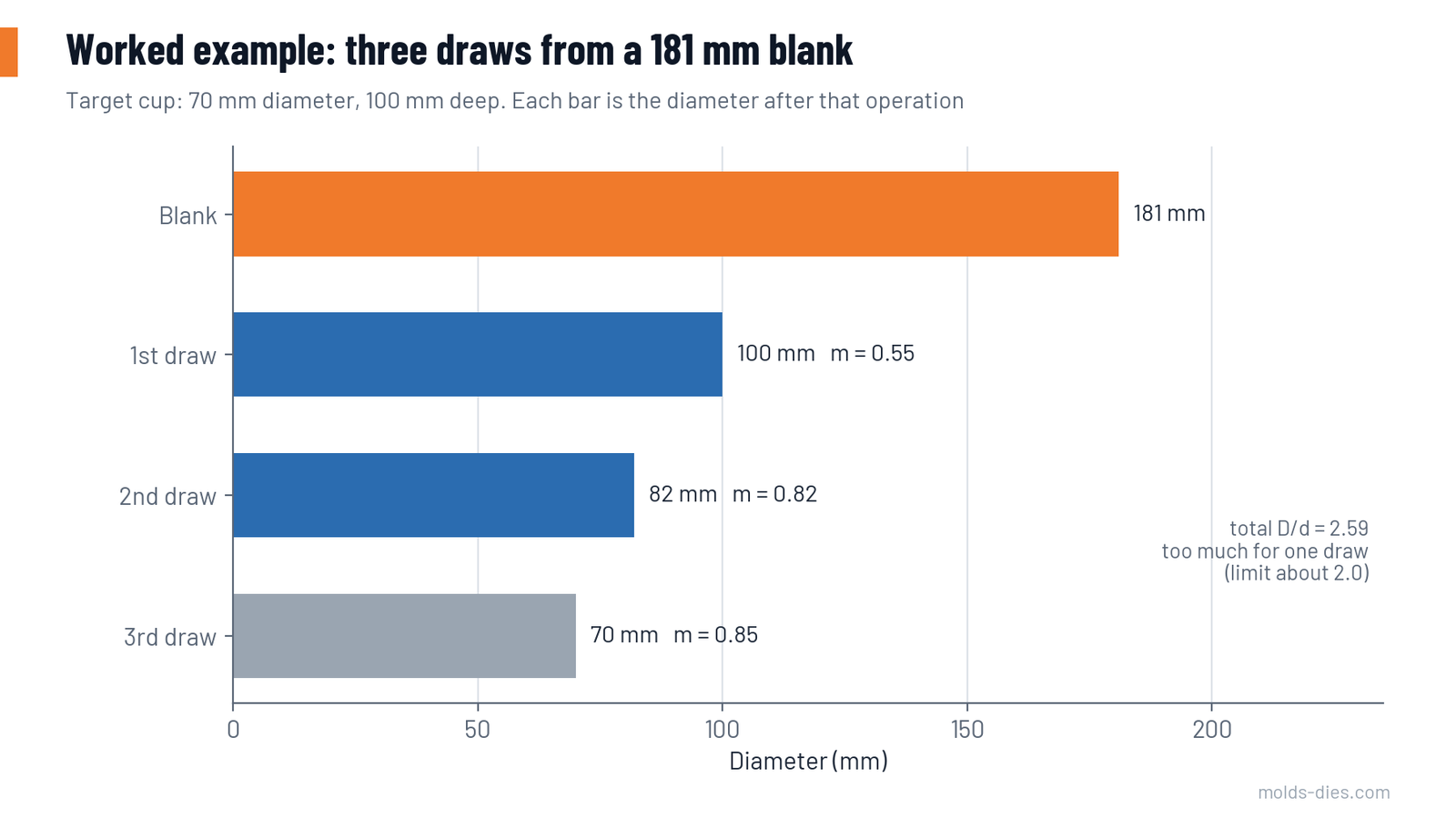
A cup of 70 mm mean diameter and 100 mm height in 1.0 mm deep-drawing steel.
| Quantity | Calculation | Result |
|---|---|---|
| Blank diameter | √(70² + 4 × 70 × 100) | 181 mm |
| Total draw ratio | 181 ÷ 70 | 2.59 |
| Total reduction needed | 70 ÷ 181 | 0.387 |
| Two draws at safe values | 0.55 × 0.78 = 0.43 | not enough (possible only at the limit values, with no margin) |
| Three draws | 0.55 × 0.82 × 0.85 = 0.383 | sufficient |
| Operation | Diameter (mm) | Cup height (mm) |
|---|---|---|
| Blank | 181 | 0 |
| First draw, m = 0.55 | 100 | 57 |
| Second draw, m = 0.82 | 82 | 79 |
| Third draw, m = 0.85 | 70 | 100 |
The height after each draw follows from the same area rule: h = (D² − d²) ÷ (4·d). Add the trimming allowance to the blank before finalizing the numbers.
Step 4: Is a blank holder needed?
A blank holder is needed whenever the sheet is thin relative to the blank. As a guide, if the thickness is less than about 2 % of the blank diameter, use one. In the example, 1.0 ÷ 181 = 0.55 %, so a blank holder is essential.
| Material | Blank holder pressure (bar) |
|---|---|
| Deep-drawing steel | 20–30 |
| Stainless steel | 20–30 or more |
| Brass | 15–20 |
| Copper | 12–18 |
| Aluminum alloys | 8–12 |
- Blank holder force = pressure × flange area under the holder
For the first draw of the example, the flange area between the 181 mm blank and about 114 mm (die opening plus radius) is roughly 15,500 mm². At 25 bar (2.5 N/mm²) the force is about 39 kN.
Too little force gives wrinkles in the flange, which are then ironed into the wall as folds. Too much force stops the flange from flowing and the cup bottom tears off. The usable range between the two becomes narrower as the draw ratio approaches its limit.
Step 5: Drawing force
- F = π × d × t × Rm × k
Rm is the tensile strength and k a factor between about 0.6 and 1.0 that rises with the draw ratio and reaches 1.0 at the limit. For the first draw of the example, with Rm = 320 N/mm² and k = 0.85:
F = 3.14 × 100 × 1.0 × 320 × 0.85 ≈ 85 kN
The press must supply the drawing force plus the blank holder force, about 125 kN here, over the whole draw depth and not only at the bottom of the stroke. That makes the energy of a mechanical press, and its force available high above bottom dead centre, the real selection criteria. Hydraulic presses and servo presses supply full force over the stroke.
Step 6: Tool radii and clearance
| Dimension | Typical value | If too small | If too large |
|---|---|---|---|
| Die radius | 5–10 × t for the first draw; smaller on redraws | High force, tearing | Flange loses holder contact early and wrinkles |
| Punch nose radius | 4–8 × t, and not smaller than the die radius where the part allows | Thinning and tearing at the bottom corner | Unsupported material puckers |
| Clearance per side | 1.1–1.25 × t | Ironing, high force, galling | Wall not controlled, bell-shaped cup |
If the finished part needs a sharper bottom radius than the first draw allows, reduce it step by step in the redraws or in a final sizing operation.
Lubrication and speed
- Lubricate the die side of the blank and the blank holder face. Keep the punch face relatively dry: friction between punch and cup bottom helps carry the load and protects the critical zone above the punch radius.
- Use lubricants with extreme-pressure additives or a dry film for stainless steel and for high draw ratios.
- Draw stainless steel and other strongly hardening materials more slowly than mild steel.
Defects and their causes
| Defect | Cause | Correction |
|---|---|---|
| Wrinkles in the flange | Blank holder force too low; die radius too large | Raise holder force; reduce die radius |
| Folds in the upper wall | Flange wrinkles drawn into the wall; clearance too large | Same as above; check clearance |
| Tear at the bottom corner | Draw ratio too high; holder force too high; radii too small; poor lubrication | Add a draw; reduce holder force; enlarge radii; improve lubrication |
| Uneven rim (earing) | Directional properties of the sheet | Allow trim; ask for material with low planar anisotropy |
| Scratches, galling | Tool surface or material unsuitable; lubricant film breaks down | Polish; coat the tools or use a bronze-type die material for stainless; better lubricant |
| Rough "orange peel" surface | Coarse grain | Specify grain size |
| Delayed cracking (stainless, brass) | Residual stress after severe draws | Anneal or stress relieve soon after drawing |
Rectangular parts
For boxes, the corners behave like a quarter of a cup and the straight sides like bends. The corner radius decides the drawability: the larger the corner radius relative to the depth, the easier the draw. A depth of more than about five to six times the corner radius usually needs more than one operation. Blank corners are trimmed back, and draw beads on the straight sides balance the flow so the sides do not feed faster than the corners.
Common mistakes
| Mistake | Result |
|---|---|
| First draw planned at the limiting ratio | Narrow process window; tearing with each harder coil |
| Blank diameter without trim allowance | Short cups after trimming |
| Same reduction in every draw | Later draws tear because the material has hardened |
| Press chosen by tonnage only | Not enough force high in the stroke; press stalls |
| Lubricant on the punch face | Bottom corner thins and tears |
Key takeaways
- Blank diameter comes from equal surface area: D = √(d² + 4·d·h), plus trim allowance.
- One draw is possible up to a ratio of about 2.0; beyond that, reduce in stages of roughly 0.55, 0.80, 0.85.
- The blank holder force must sit between wrinkling and tearing, and that range narrows near the limit.
- Die radius of 5–10 thicknesses, punch radius of 4–8, and clearance of 1.1–1.25 thicknesses are sound starting values.
Related Articles
Punch and Die Steels: Grade, Hardness and Coating by Application
How to choose tool steel, hardness and coating for punches and dies from the failure mode: wear, chipping, galling or cracking.
Cutting Force, Stripping Force and Press Tonnage: How to Calculate
Formulas and a worked example for blanking and piercing force, stripping force, the effect of shear angle, and choosing press tonnage.
Springback in Bending: Prediction and Compensation
What controls springback in sheet metal bending, how to estimate it from material and R/t ratio, and the die design methods used to compensate for it.
Strip Layout for Progressive Dies: Material Utilization, Pilots and Carriers
How to develop a progressive die strip layout: part orientation, pitch and bridge widths, material utilization, pilot holes, carriers and station sequence.
Sheet Metal Material Selection: HR vs. CR Steel
Compare hot-rolled and cold-rolled steel for sheet metal design. Understand differences in cost, finish, strength, and forming performance to select the right material.
Understanding Press Machines in Sheet Metal Operations
Explore the different types of press machines used in sheet metal manufacturing—manual, hydraulic, pneumatic, eccentric, and press brake—with practical comparisons and engineering insights.
Introduction to Sheet Metal Die Design: Processes, Principles, and Applications
An essential introduction to sheet metal die design, covering key processes like shearing, bending, and forming for efficient manufacturing.