Springback in Bending: Prediction and Compensation
-
 Mohamed Aboelfotouh
- Sector : Sheet Metal
- Oct. 2, 2026, 4:11 p.m.
Every bent sheet metal part opens up slightly when the tool releases it. This is springback. If the die is built to the drawing angle, the part comes out wrong by that amount. With mild steel the error is a degree or two and easy to absorb. With stainless steel, hard aluminum tempers and high-strength steels it can be several degrees and vary from coil to coil. This article explains what controls springback, how to estimate it, and how to remove it in the die.
What happens in the bend
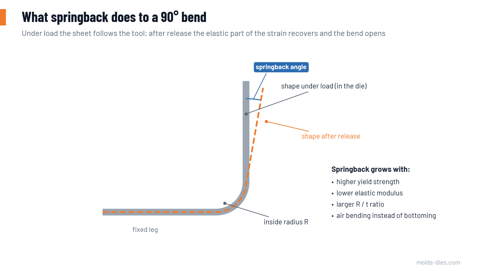
When sheet is bent, the outer fibres are stretched and the inner fibres compressed. Most of that strain is permanent (plastic), but a part of it is elastic. A band around the middle of the thickness is never stressed beyond the elastic limit at all. When the tool releases the part, the elastic strain recovers: the bend angle decreases and the bend radius becomes slightly larger.
The factors
| Factor | Effect on springback | Why |
|---|---|---|
| Higher yield strength | More | More elastic strain is stored before the material yields |
| Lower elastic modulus | More | The same stress gives more elastic strain; aluminum has about one third of the modulus of steel |
| Larger ratio of inside radius to thickness (R/t) | More | A gentle bend leaves a larger share of the thickness elastic |
| Thinner sheet at the same radius | More | Same as a larger R/t |
| Smaller bend angle | Less in degrees, but a larger share of the angle | Less bent length |
| Air bending | More | Material is only bent, with no compression of the bend zone |
| Bottoming or coining | Less, sometimes slightly negative | The bend zone is yielded through its whole thickness |
| Wider die opening in air bending | More | Larger natural radius |
The two ratios that matter most are yield strength divided by elastic modulus (the material) and R/t (the geometry).
Estimating springback
A commonly used first estimate relates the radius before release (Ri) to the radius after release (Rf):
- Ri ÷ Rf = 4·x³ − 3·x + 1, where x = (Ri × Y) ÷ (E × t)
Y is the yield strength, E the elastic modulus and t the thickness. The angle after release is then:
- Angle after = angle under load × (Ri + t/2) ÷ (Rf + t/2)
Example. Austenitic stainless steel 304, t = 1.0 mm, bent to 90° over Ri = 4.0 mm. E = 193,000 N/mm². The initial yield strength is about 300 N/mm², but the material work-hardens strongly, so the flow stress in the bend is taken as about 600 N/mm².
| Step | Calculation | Result |
|---|---|---|
| x | 4.0 × 600 ÷ (193,000 × 1.0) | 0.0124 |
| Ri ÷ Rf | 4 × 0.0124³ − 3 × 0.0124 + 1 | 0.9627 |
| Rf | 4.0 ÷ 0.9627 | 4.155 mm |
| Angle after release | 90 × 4.5 ÷ 4.655 | 87.0° |
| Springback | 90 − 87.0 | 3.0° |
With the initial yield strength of 300 N/mm², the same formula gives only 1.5°, which is too low. The formula ignores work hardening, so always use the flow stress at the bend strain for materials that harden strongly. Treat the outcome as a starting value for the die, to be confirmed at try-out.
Typical values
Indicative springback for 90° bends in a V-die without bottoming:
| Material | R/t up to 1 | R/t of 2 to 5 |
|---|---|---|
| Soft aluminum, soft copper | 0–1° | 1–2° |
| Low-carbon steel | 0.5–1.5° | 1–3° |
| Austenitic stainless steel (304) | 1.5–3° | 3–5° |
| Aluminum in hard tempers (5xxx-H3x, 6061-T6) | 2–4° | 4–8° |
| High-strength low-alloy steel | 2–4° | 4–7° |
| Dual-phase and other advanced high-strength steels | 3–6° | 6–12° or more |
These ranges are wide because strength varies within a grade. That variation is the real difficulty: a die can be adjusted to any constant springback, but not to one that changes with each coil.
Compensation in the die
| Method | How it works | Advantages | Limits |
|---|---|---|---|
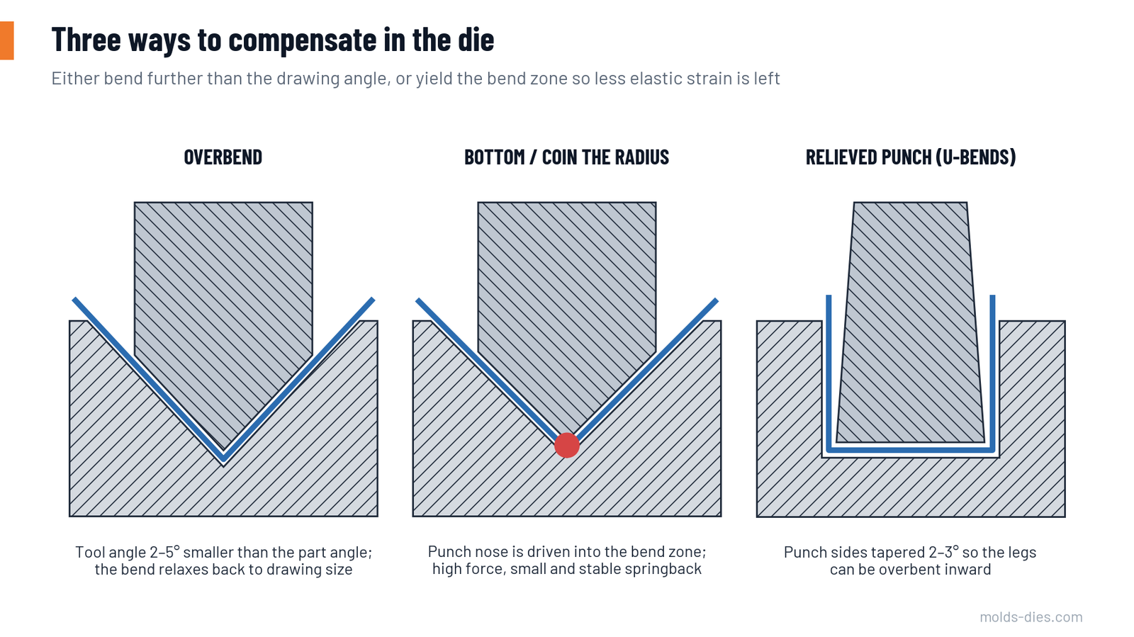
| Overbending | Tool angle is smaller than the part angle by the expected springback | Simple; low force | Sensitive to material variation; needs space to overbend |
| Bottoming | Punch presses the sheet fully against the die at the end of the stroke | More consistent than air bending | Higher force; tool angle must still include some compensation |
| Coining the radius | Punch nose, or a small bead on it, is driven into the bend zone | Springback small and stable | Force several times that of air bending; thins the material; marks the inside radius |
| Relieved punch for U-bends | Punch sides tapered inward 2–3° so the legs can be overbent | Works in a simple wipe-down die | Fixed amount of compensation |
| Rotary or rocker bender | A rotating element wraps the flange past 90° | Adjustable; low marking | Space and cost |
| Cam-driven overbend | A side cam pushes the flange beyond the final angle | Any angle; adjustable with shims | Die complexity |
| Stretch during bending | Tension added with draw beads, stake beads or a blank holder so the whole thickness yields in tension | Very effective on channels in high-strength steel | Needs extra material and force; risk of splitting |
| Stiffening features | Darts or ribs across the bend line | Locks the angle; also stiffens the part | Must be allowed by the part design |
| Restrike station | A second hit that sets the final angle | Separates forming from calibration | One more station |
For progressive and transfer dies running varying material, build in adjustment: shims under form blocks, adjustable cams, or a restrike station whose depth can be set. A die with fixed compensation is correct for only one coil.
Design choices that reduce the problem
- Use the smallest bend radius the material tolerates. A smaller R/t leaves less elastic core. Check the minimum bend radius for the material and grain direction to avoid cracking.
- Bend across the grain where the layout allows; the minimum radius is smaller in that direction.
- Specify the material tightly when angles are critical: a narrower yield strength range from the supplier is often cheaper than scrap.
- Tolerance the angle realistically. ±0.5° on a mild steel bracket is achievable in a good die; the same tolerance on a high-strength channel needs calibration features or a restrike.
- Keep flanges long enough to be gripped and overbent. As a guide, the flange should be at least four times the thickness plus the bend radius.
Try-out procedure
| Step | Action |
|---|---|
| 1 | Record the coil data: grade, thickness, yield and tensile strength from the certificate |
| 2 | Run parts and measure the angle on at least five pieces, away from the ends of the bend |
| 3 | Adjust the compensation by the measured error, not by the full theoretical value |
| 4 | Repeat with material from a second coil, ideally from the other end of the strength range |
| 5 | Set the adjustment in the middle and note the shim or setting values on the die card |
| 6 | Define a check interval in production, and re-check at every coil change |
Sources of variation in production
| Source | Typical effect | Control |
|---|---|---|
| Yield strength between coils | The largest contributor | Material specification; coil certificates; adjustment in the die |
| Thickness tolerance | Changes R/t and, in bottoming dies, the amount of coining | Thickness check at coil change |
| Tool wear on radii | Radius grows, springback grows | Inspection at die service |
| Press shut height and stiffness | Changes bottoming pressure | Fixed shut-height setting; tonnage monitor |
| Lubrication and temperature | Minor | Consistent practice |
Common mistakes
| Mistake | Result |
|---|---|
| Building form steels to the drawing angle | Every part out of angle from the first trial |
| Compensating from a formula without a trial | Over- or under-correction |
| Fixed compensation for a material with wide strength range | Angle drifts with each coil |
| Large bend radius chosen "to be safe" on high-strength steel | Maximum springback and poor repeatability |
| Coining with a press that lacks the force | Inconsistent angle; press overload |
Key takeaways
- Springback rises with yield strength, falls with elastic modulus, and rises with R/t.
- Estimate it for the first die design, then measure it at try-out on more than one coil.
- Overbending is the simplest compensation; bottoming, coining and stretching make the result more stable.
- For strong or variable materials, make the compensation adjustable and specify the material tightly.
Related Articles
Punch and Die Steels: Grade, Hardness and Coating by Application
How to choose tool steel, hardness and coating for punches and dies from the failure mode: wear, chipping, galling or cracking.
Cutting Force, Stripping Force and Press Tonnage: How to Calculate
Formulas and a worked example for blanking and piercing force, stripping force, the effect of shear angle, and choosing press tonnage.
Deep Drawing: Draw Ratio, Blank Size and Number of Draws
How to calculate blank diameter, draw ratio, number of draws, blank holder force and tool radii for cylindrical deep-drawn parts.
Strip Layout for Progressive Dies: Material Utilization, Pilots and Carriers
How to develop a progressive die strip layout: part orientation, pitch and bridge widths, material utilization, pilot holes, carriers and station sequence.
Sheet Metal Material Selection: HR vs. CR Steel
Compare hot-rolled and cold-rolled steel for sheet metal design. Understand differences in cost, finish, strength, and forming performance to select the right material.
Understanding Press Machines in Sheet Metal Operations
Explore the different types of press machines used in sheet metal manufacturing—manual, hydraulic, pneumatic, eccentric, and press brake—with practical comparisons and engineering insights.
Introduction to Sheet Metal Die Design: Processes, Principles, and Applications
An essential introduction to sheet metal die design, covering key processes like shearing, bending, and forming for efficient manufacturing.