Cutting Force, Stripping Force and Press Tonnage: How to Calculate
-
 Mohamed Aboelfotouh
- Sector : Sheet Metal
- Oct. 2, 2026, 6:38 p.m.
Before a blanking or piercing die is designed, three numbers are needed: the force to cut the material, the force to strip it off the punches, and the size of press that can deliver both with a margin. The calculation is short, but several details are regularly missed: the shear strength used, the effect of shear angles, the point in the stroke where the press delivers its rated force, and the reverse load when the material breaks. This article covers them in order with one worked example.
Cutting force
- F = L × t × τ
| Symbol | Meaning | Unit |
|---|---|---|
| L | Total length of cut: the perimeter of every edge cut in the same stroke | mm |
| t | Sheet thickness | mm |
| τ | Shear strength of the material | N/mm² |
| F | Cutting force | N (divide by 1,000 for kN; 9.81 kN ≈ 1 tonne-force) |
Add up all edges cut at the same instant: the blank outline, every pierced hole, every notch, and in a progressive die, the cuts in all stations.
Shear strength
If the shear strength is not on the material certificate, estimate it from the tensile strength.
| Material | Shear strength as a share of tensile strength | Typical shear strength (N/mm²) |
|---|---|---|
| Low-carbon steel | 0.75–0.85 | 260–350 |
| High-strength low-alloy steel | 0.7–0.8 | 350–500 |
| Austenitic stainless steel | 0.75–0.85 | 480–560 |
| Aluminum, soft (1xxx-O, 3xxx-O) | 0.6–0.7 | 60–100 |
| Aluminum, hard (5052-H32, 6061-T6) | 0.6–0.7 | 140–210 |
| Copper, soft | 0.65–0.75 | 150–180 |
| Brass, half hard | 0.65–0.75 | 240–300 |
Use the upper end of the strength range the material specification allows, not the typical value. A die sized for average material will be overloaded by a strong coil. Worn cutting edges and tight clearances raise the force further, by 10–30 %.
Stripping force
After the cut, the material grips the punch and must be pushed off by the stripper.
| Condition | Stripping force as a share of cutting force |
|---|---|
| Thin material, normal clearance, sharp tools | 5–8 % |
| General work | 10 % |
| Thick material, small clearance, holes close together, sticky materials (stainless, soft aluminum) | 15–20 % |
In a spring-stripper die, the springs are compressed during the working stroke, so their force adds to the press load. Include it. The same applies to pressure pads, nitrogen cylinders and any forming done in the same stroke.
Worked example
A blank 80 × 50 mm with four 8 mm holes, cut in one stroke from 1.5 mm low-carbon steel with a shear strength of 320 N/mm².
| Quantity | Calculation | Result |
|---|---|---|
| Outline perimeter | 2 × (80 + 50) | 260 mm |
| Hole perimeter | 4 × 3.14 × 8 | 100.5 mm |
| Total cut length L | 260 + 100.5 | 360.5 mm |
| Cutting force | 360.5 × 1.5 × 320 | 173,000 N = 173 kN |
| Stripping force (10 %) | 0.10 × 173 | 17 kN |
| Press load | 173 + 17 | 190 kN |
| Press size at 75 % loading | 190 ÷ 0.75 | 253 kN |
| Choice | next standard size | 300–400 kN (30–40 tonnes) |
The Punching Die Cutting Force Calculator on this site performs the same calculation.
Reducing the peak force
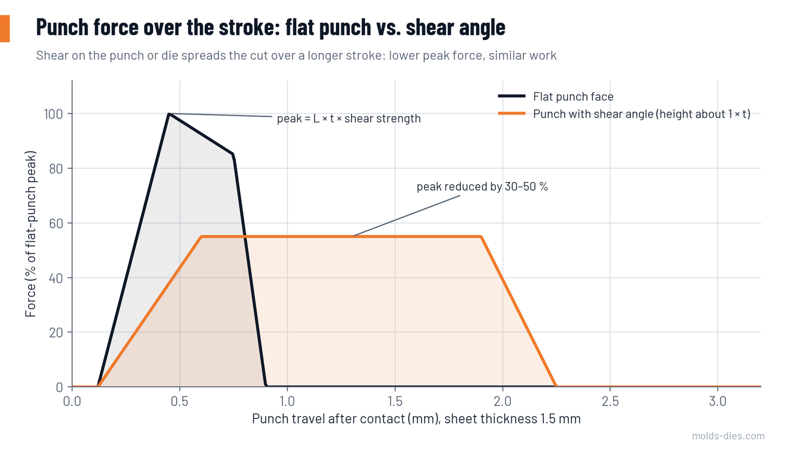
With flat punch faces, the whole perimeter is cut at once. The force rises to its peak in the first third of the thickness and then collapses when the material fractures. Two methods spread the cut over more of the stroke.
Shear angle. The punch face or the die face is ground at an angle so the cut progresses along the edge, like scissors.
| Shear height | Approximate peak force compared with flat tools |
|---|---|
| None | 100 % |
| About 0.5 × t | 70–75 % |
| About 1 × t | 50–65 % |
| About 2 × t | 30–40 % |
- Put the shear on the punch when piercing: the slug is bent and scrapped, and the hole stays flat.
- Put the shear on the die when blanking: the blank stays flat and the strip is distorted.
- Use a symmetrical (roof or hollow) shear so there is no side thrust on the punch.
Staggered punches. Punches of different lengths enter the material one after another. Make the steps about half to one sheet thickness. Keep the large punches long and the small, slender punches short, so the small ones enter material that is already held and are not deflected.
Neither method reduces the work done per stroke. Force is lower but acts over a longer distance. A press that lacks energy will not be helped.
Choosing the press
Force is only the first criterion.
| Criterion | What to check |
|---|---|
| Rated force | Load not more than 70–80 % of the rated force for continuous production |
| Rating point | A mechanical press delivers its rated force only within a few millimetres above the bottom of the stroke. Thick material, shear angles and drawing operations need force higher in the stroke, where less is available. Check the press force curve |
| Energy | Work per stroke ≈ cutting force × penetration to fracture (about 30–60 % of the thickness) plus stripping and forming work. Flywheel energy must cover it at the planned stroke rate; slowing the press reduces available energy |
| Reverse load (snap-through) | When the material fractures, the stored stretch of the press frame is released as a shock in the opposite direction. Mechanical presses usually tolerate about 10 % of their capacity as reverse load. Shear angles, staggering and hydraulic dampers reduce it |
| Load centre | The resultant of all forces should be close to the centre of the ram; off-centre loading tilts the ram and wears punches on one side |
| Bed size, shut height, stroke | Die dimensions, strip lift and part removal |
| Speed | Strokes per minute against feed length and material thickness |
Finding the load centre
In a die with several cuts, the centre of force is the weighted average of the positions of the individual forces:
- X = Σ(Fᵢ × xᵢ) ÷ ΣFᵢ, and the same for Y
Since each force is proportional to its cut length at constant thickness, the cut lengths can be used directly. Place the die on the press so this point is on the ram centre line, or as close as the strip feed allows. In progressive dies, add forming and drawing forces at their stations.
Other forces to remember
| Force | Estimate |
|---|---|
| Bending in a V-die (air bending) | Roughly width × t² × tensile strength × 1.2–1.4 ÷ die opening |
| Wipe bending | Roughly one third of width × t × tensile strength, plus the pad force holding the part |
| Pad and blank holder forces | From the spring or cylinder data at working compression |
| Coining and embossing | Area × several times the yield strength; can exceed all cutting forces |
Common mistakes
| Mistake | Consequence |
|---|---|
| Using tensile strength instead of shear strength | Force overestimated by 20–40 %; oversized press |
| Using typical instead of maximum strength | Die overloaded by strong coils |
| Forgetting holes and notches in the cut length | Force underestimated |
| Ignoring spring-stripper and pad forces | Press overloaded near the bottom of the stroke |
| Selecting a press at 100 % of its rated force | Bearing and frame wear, snap-through damage |
| Assuming a shear angle saves energy | Press stalls at high stroke rates |
| Shear on the punch for blanking | Bent blanks |
Key takeaways
- Cutting force is cut length × thickness × shear strength; shear strength is about 0.8 of tensile strength for steel and 0.6–0.7 for aluminum.
- Add 5–20 % for stripping and include spring, pad and forming forces.
- Load the press to 70–80 % of its rating, and check the rating point, the energy and the reverse load.
- Shear angles and staggered punches cut the peak force by up to half, but not the work.
Related Articles
Punch and Die Steels: Grade, Hardness and Coating by Application
How to choose tool steel, hardness and coating for punches and dies from the failure mode: wear, chipping, galling or cracking.
Deep Drawing: Draw Ratio, Blank Size and Number of Draws
How to calculate blank diameter, draw ratio, number of draws, blank holder force and tool radii for cylindrical deep-drawn parts.
Springback in Bending: Prediction and Compensation
What controls springback in sheet metal bending, how to estimate it from material and R/t ratio, and the die design methods used to compensate for it.
Strip Layout for Progressive Dies: Material Utilization, Pilots and Carriers
How to develop a progressive die strip layout: part orientation, pitch and bridge widths, material utilization, pilot holes, carriers and station sequence.
Sheet Metal Material Selection: HR vs. CR Steel
Compare hot-rolled and cold-rolled steel for sheet metal design. Understand differences in cost, finish, strength, and forming performance to select the right material.
Understanding Press Machines in Sheet Metal Operations
Explore the different types of press machines used in sheet metal manufacturing—manual, hydraulic, pneumatic, eccentric, and press brake—with practical comparisons and engineering insights.
Introduction to Sheet Metal Die Design: Processes, Principles, and Applications
An essential introduction to sheet metal die design, covering key processes like shearing, bending, and forming for efficient manufacturing.