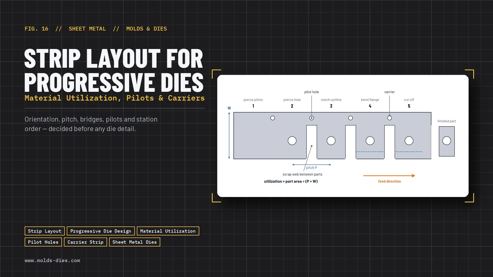
Strip Layout for Progressive Dies: Material Utilization, Pilots and Carriers
-
 Mohamed Aboelfotouh
- Sector : Sheet Metal
- Oct. 2, 2026, 4:10 p.m.
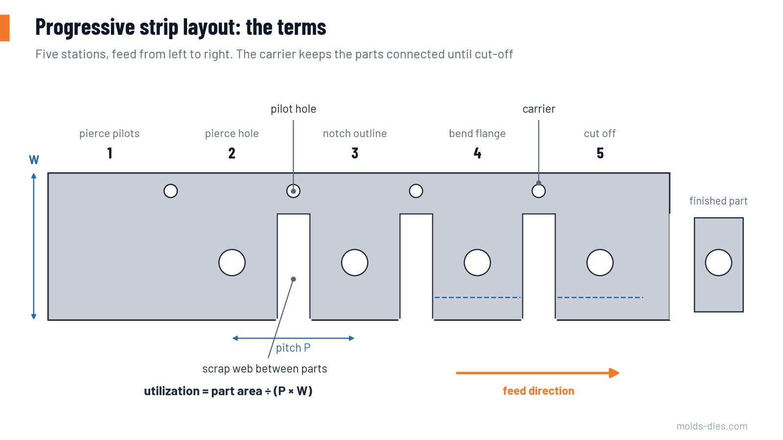
The strip layout is the plan of a progressive die: it shows how the part develops from the flat strip, station by station, until it is cut free. It fixes the material cost per part, the number of stations, the size of the die and the press it needs. Mistakes made here cannot be repaired later by good die detailing. This article goes through the decisions in the order they are normally taken.
The terms
| Term | Meaning |
|---|---|
| Pitch (progression) | Distance the strip advances at each press stroke |
| Strip width | Width of the coil or sheared strip |
| Scrap web (bridge) | Material left between two neighbouring blanks |
| Edge margin | Material left between the blank and the strip edge |
| Carrier | The part of the strip that stays intact and carries the parts from station to station |
| Pilot | A pin that enters a pierced hole to position the strip exactly before the tools engage |
| Idle station | A station where no work is done, left to give the die strength or space |
Step 1: Develop the flat blank
Unfold the part to its flat shape using the bend allowance for the material and radii. Mark on it:
- the grain (rolling) direction limits for each bend;
- the burr side required by the drawing;
- holes and edges with tight tolerances relative to each other;
- features that can only be made after forming (holes close to a bend, for example).
Step 2: Choose the orientation
Try the blank on the strip in several positions: lengthwise, crosswise, angled, and nested in pairs. Judge each by four criteria.
| Criterion | What to look for |
|---|---|
| Material utilization | Highest share of the strip that ends up as parts |
| Grain direction | Bend lines across the grain, or at least 45° to it, for tight radii and for strong materials |
| Carrier attachment | A place where the part can stay connected to the carrier until the last station |
| Feeding and lifting | Formed features that do not block the strip from lifting and advancing |
The orientation with the best utilization is not always the best choice. A layout that saves 3 % of material but needs cams to form sideways may cost more over the die's life.
Step 3: Set the web and edge margins
The webs must be strong enough for the strip to be fed and piloted without buckling, and wide enough for the scrap to be cut cleanly. Typical minimum values:
| Sheet thickness t (mm) | Web between parts (mm) | Edge margin (mm) |
|---|---|---|
| 0.5 | 1.0 | 1.2 |
| 1.0 | 1.2 | 1.5 |
| 1.5 | 1.8 | 2.0 |
| 2.0 | 2.2 | 2.5 |
| 3.0 | 3.0 | 3.5 |
As a rule of thumb the web is 1 to 1.5 times the sheet thickness, with an absolute minimum of about 1 mm. Increase the values for soft materials, for long blank edges running parallel to each other, and for hand-fed strips.
Step 4: Calculate pitch, width and utilization
- Pitch = blank length in the feed direction + web
- Strip width = blank width across the strip + 2 × edge margin (+ carrier width, if the carrier is outside the blank)
- Utilization = blank area × parts per pitch ÷ (pitch × strip width)
Worked example. A blank 40 × 25 mm with an area of 880 mm², in 1.0 mm steel.
| Layout | Pitch (mm) | Strip width (mm) | Area per part (mm²) | Utilization | Steel per part (g) |
|---|---|---|---|---|---|
| A: 25 mm side along the feed | 26.5 | 44.0 | 1,166 | 75.5 % | 9.15 |
| B: 40 mm side along the feed | 41.5 | 29.0 | 1,204 | 73.1 % | 9.45 |
Layout A saves 0.30 g per part. Over one million parts that is 300 kg of steel. It also has the shorter pitch, which means a shorter die and a faster feed. Layout B would be chosen only if the grain direction or the carrier required it.
Most single-row layouts fall between 60 and 80 % utilization. Two-row or nested layouts can exceed that, at the cost of a wider die and a part that leaves the die in two orientations.
Step 5: Plan the pilots
Feeders are not accurate enough to position the strip for precise work. The pilots do the final positioning.
- Pierce the pilot holes in the first station and use them in every following station that needs accuracy.
- Place pilots as far apart as possible, ideally on both sides of the strip, to control position and rotation.
- Prefer holes in the carrier or in the scrap. Use holes in the part only if their tolerance and appearance allow slight marking.
- Let the pilots enter before any punch touches the strip. The pilot nose should project beyond the stripper face by at least the sheet thickness.
- Release the feed just before the pilots enter, so the strip is free to move into position.
- Size the pilot a few hundredths of a millimetre smaller than the pierced hole: about 0.02–0.05 mm for precise work, more for general work.
Step 6: Choose the carrier
| Carrier type | Description | Use |
|---|---|---|
| One-sided | Solid strip along one edge; part attached by a tab | Parts formed on the free side; simple and stiff |
| Two-sided (ladder) | Carriers on both edges with the part between them | Best control; parts with forming in the middle |
| Centre carrier | Narrow strip down the middle; part hangs on both sides | Parts formed on both edges |
| Stretch web | Carrier connected by thin, curved links that can deform | Drawn or deeply formed parts, where material is pulled in and the pitch between parts would otherwise change |
| Scrap-web carrier | The web between blanks is the carrier | Flat blanks, simple parts |
The carrier must be stiff enough to push the strip through the die without buckling, and its connection to the part must be placed where the final cut leaves an acceptable edge.
Step 7: Sequence the stations
| Rule | Reason |
|---|---|
| Pierce pilots first | Every later operation is positioned from them |
| Pierce holes before forming, except holes close to a bend | Flat material is pierced more accurately; holes within about two thicknesses plus the bend radius of a bend line distort and should be pierced after forming or protected by a relief |
| Cut complex outlines in several steps | Stronger punches and die sections; easier sharpening |
| Leave idle stations where die sections would be weak | Thin steel between openings cracks; idle stations also leave room for later changes |
| Avoid slivers | Each scrap piece should be at least about 1.5 times the sheet thickness wide, or it will pull up and jam |
| Overlap successive cuts slightly | A small mismatch notch avoids a burr or step where two cuts meet |
| Form in a direction that lets the strip lift and advance | Check the lift height needed to clear the formed shapes |
| Balance the forces around the press centre | Off-centre load tilts the ram and wears the die on one side |
| Cut off or blank through last | The part stays controlled until the end |
Step 8: Check the layout before design continues
| Question | Yes / No |
|---|---|
| Does every slug and scrap piece fall freely through the die? | |
| Can the strip lift, advance and settle without catching? | |
| Is each pilot hole pierced before it is needed? | |
| Is the steel between die openings thick enough in every station? | |
| Are the bends oriented acceptably to the grain? | |
| Is the burr on the side the drawing allows? | |
| Is the total force, and its centre, suitable for the planned press? | |
| Is there room to add a station if a forming step has to be split? | |
| Can the finished part and the last scrap leave the die reliably? |
Common mistakes
| Mistake | Consequence |
|---|---|
| Choosing the layout by utilization alone | Bends crack along the grain, or cams are needed |
| Webs below the minimum | Strip buckles at the feed; misfeeds |
| Pilots only on one side | Strip rotates; hole-to-edge dimensions vary |
| All operations packed into the minimum number of stations | Weak die sections, no room for corrections |
| Forgetting the strip lift | Formed features collide with the die on feeding |
| No plan for scrap removal | Slugs stack up and break punches |
Key takeaways
- Develop the blank, then compare several orientations on utilization, grain, carrier attachment and feeding.
- Use webs of about 1 to 1.5 times the thickness and calculate utilization as blank area over pitch times strip width.
- Pierce pilots first, place them far apart, and let them enter before the punches.
- Sequence for strength and control: pierce before forming, split complex cuts, keep idle stations, and cut off last.
Related Articles
Punch and Die Steels: Grade, Hardness and Coating by Application
How to choose tool steel, hardness and coating for punches and dies from the failure mode: wear, chipping, galling or cracking.
Cutting Force, Stripping Force and Press Tonnage: How to Calculate
Formulas and a worked example for blanking and piercing force, stripping force, the effect of shear angle, and choosing press tonnage.
Deep Drawing: Draw Ratio, Blank Size and Number of Draws
How to calculate blank diameter, draw ratio, number of draws, blank holder force and tool radii for cylindrical deep-drawn parts.
Springback in Bending: Prediction and Compensation
What controls springback in sheet metal bending, how to estimate it from material and R/t ratio, and the die design methods used to compensate for it.
Sheet Metal Material Selection: HR vs. CR Steel
Compare hot-rolled and cold-rolled steel for sheet metal design. Understand differences in cost, finish, strength, and forming performance to select the right material.
Understanding Press Machines in Sheet Metal Operations
Explore the different types of press machines used in sheet metal manufacturing—manual, hydraulic, pneumatic, eccentric, and press brake—with practical comparisons and engineering insights.
Introduction to Sheet Metal Die Design: Processes, Principles, and Applications
An essential introduction to sheet metal die design, covering key processes like shearing, bending, and forming for efficient manufacturing.