3D Printed Mold Inserts for Short-Run Injection Molding
-
 Mohamed Aboelfotouh
- Sector : Additive Manufacturing
- Oct. 9, 2026, 6:15 a.m.
A steel injection mold takes weeks and an aluminum prototype mold takes one to two weeks. A printed polymer insert can be on the machine the day after the design is released. It will not last long and it will not hold tight tolerances, but it produces real molded parts in the real plastic. This article explains where printed inserts fit, how to design and run them, and what life to expect.
Where printed inserts fit
| Suitable | Not suitable |
|---|---|
| 10–100 parts for functional tests, assembly trials or approval samples | Tolerances tighter than about ±0.1–0.2 mm |
| Parts that must be in the production plastic, for example PP, TPE or ABS | Glass-filled or high-temperature plastics in quantity |
| Small parts, roughly up to 150 mm and shot weights of tens of grams | Large parts with high clamping force |
| Designs that are still changing | Validation of cycle time, shrinkage or warpage for the production mold |
The last point is often missed. A polymer insert conducts heat about a hundred times more slowly than steel. The part cools slowly, so its shrinkage, crystallinity and warpage differ from parts out of a steel mold. Printed inserts answer the question "does the design work in this material?" They do not answer "what will the production mold deliver?"
Insert materials and processes
| Insert type | Strength | Weakness | Typical use |
|---|---|---|---|
| SLA, ceramic- or glass-filled high-temperature resin | Stiff, high heat deflection temperature, smooth surface | Brittle; thin cores and sharp edges chip | Most short-run inserts |
| Material jetting, ABS-like resin | Smooth surface, fine detail, tougher | Lower temperature resistance; needs cooling between shots | Low-temperature plastics, fine detail |
| Powder bed nylon | Tough | Rough, porous surface; parts stick | Rarely used for cavities |
| Filament extrusion | Cheap, large | Layer lines, low accuracy | Not recommended for cavities |
| Machined aluminum (for comparison) | Thousands of shots, real cycle | One to two weeks, higher cost | Bridge tooling |
Print the cavity surface facing up or vertical so that it carries no support marks, and print with the finest layer the schedule allows. Light sanding of layer lines in the draw direction improves release.
The insert and its frame
A printed insert should never take the clamping force alone. It sits in the pocket of a steel or aluminum frame, which carries the clamp load, the guide pins, the sprue bushing and the ejector system. The frame is made once and reused for every job.
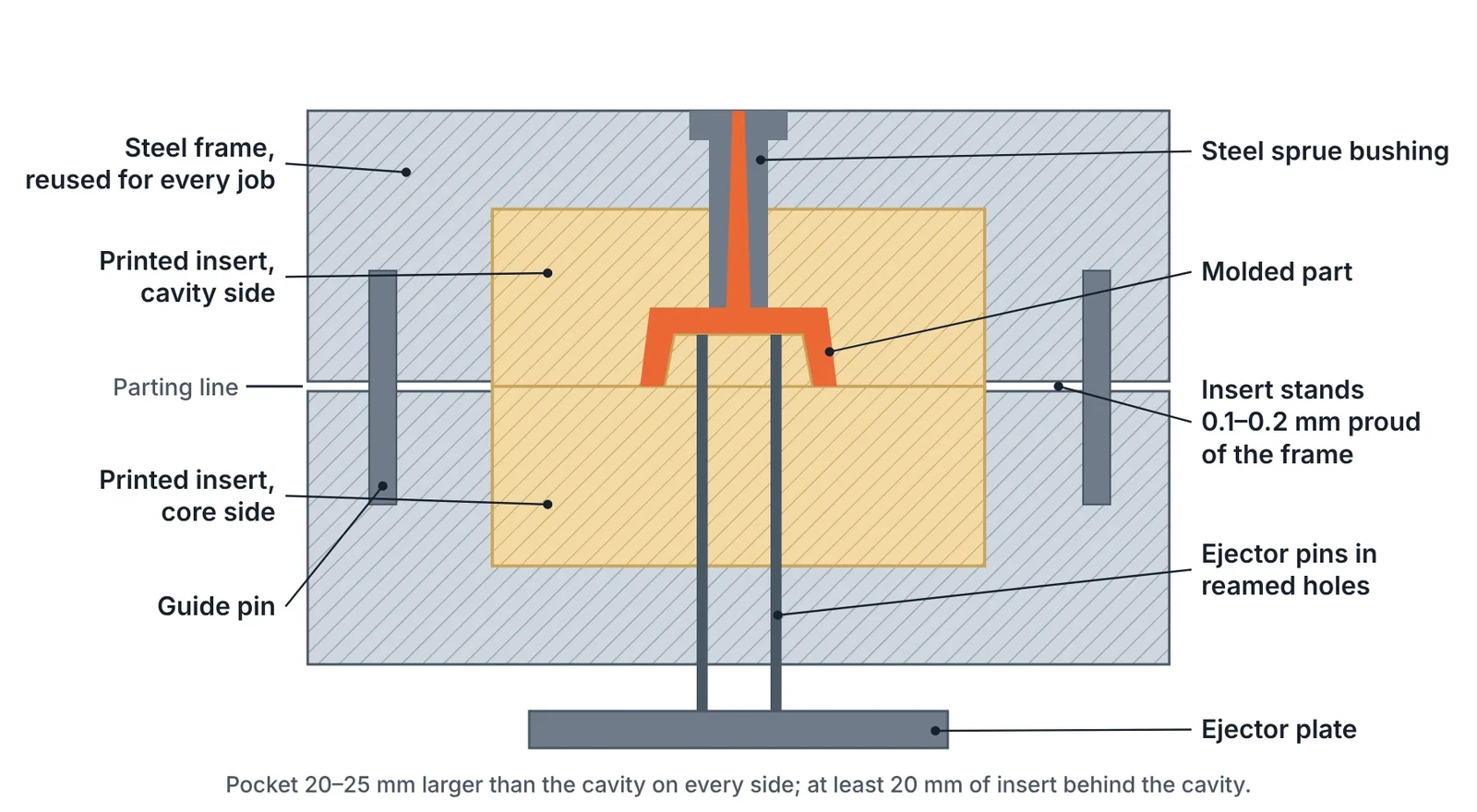
- Pocket. The frame pocket should be 20–25 mm larger than the cavity on every side, so that the insert has thick walls around the cavity.
- Fit. Print the insert about 0.5 mm oversize on the side faces and machine it to fit the pocket without play.
- Height. The insert stands 0.1–0.2 mm above the frame face so that the parting faces of the inserts seal before the frames touch.
- Thickness. Keep at least 20 mm of insert thickness behind the cavity in the clamping direction and support the full back face.
- Ejector and sprue holes. Print them 0.2–0.3 mm undersize and ream them at assembly. Keep holes at least 3 mm from any edge.
Design changes compared with a steel mold
| Feature | Steel mold practice | Printed insert |
|---|---|---|
| Draft | 0.5–2° | 5° where the part allows; never below 2–3° |
| Gate type | Any, including tunnel and pin gates | Sprue, edge, fan or tab gates only |
| Gate size | Standard | 2–3 times larger; edge gate as thick as the wall |
| Runner system | Cold or hot runner | Cold runner only |
| Core pins | Slender pins possible | Height to diameter up to 3:1; above that use steel pins |
| Small holes | As designed | Below about 1 mm, drill after printing or use steel pins |
| Corners | Sharp where needed | Radii on every thin feature and corner |
| Shut-offs | Fitted steel to steel | Simple, near-perpendicular faces; avoid long sliding shut-offs |
| Side actions | Slides and lifters | Hand-loaded loose inserts |
Large gates and generous draft do most of the work. A large gate lets the cavity fill at low pressure, and draft lets the part release without pulling on the insert. The principles of gate choice are in Gate Types and Gate Location: How to Choose.
Process settings
The aim is to fill the cavity with the lowest pressure and temperature that give a complete part.
- Melt temperature. Start at the low end of the range recommended for the plastic.
- Injection speed. Start slow, at 10–20 % of the machine maximum.
- Short shots first. Begin at about 75 % of the part volume with no holding pressure and increase in small steps until the cavity is about 90 % full.
- Holding pressure. Then add holding pressure at 30–50 % of the injection pressure, only as much as the part needs.
- Clamping force. Calculate it from the projected area and the low cavity pressure, add 10 %, and do not use more. Excess clamp force crushes the parting face.
- Mold closing. Close fast until just before contact, then slowly.
- Cooling. Blow compressed air on both halves after each shot until the surface is back to about 50 °C. Cycle times of two to five minutes are normal.
- Release agent. Apply at the start and every few shots.
Clamping force example. A part with a projected area of 40 cm² including the runner is filled at a cavity pressure of 250 bar. The opening force is 40 cm² × 250 bar = 100 kN, about 10 tonnes. With a 10 % margin the clamp is set to 11 tonnes. The same part in a steel mold at 500 bar would be clamped at twice that. The clamping force calculator gives the value for other cases.
Cooling channels in a polymer insert have little effect on cycle time because the insert material insulates. Simple straight channels 8–10 mm below the surface can extend insert life, but air cooling between shots is the main control.
Expected insert life
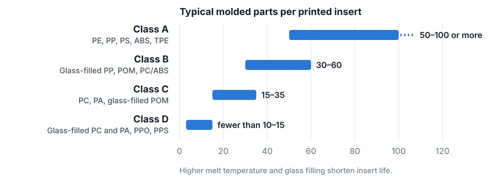
Life depends mainly on the melt temperature and abrasiveness of the plastic, and then on geometry. The values below are typical for a well-designed insert with generous draft and large gates.
| Class | Plastics | Typical parts per insert |
|---|---|---|
| A | PE, PP, PS, ABS, TPE | 50–100 or more |
| B | Glass-filled PP, POM, PC/ABS | 30–60 |
| C | PC, PA, glass-filled POM | 15–35 |
| D | Glass-filled PC and PA, PPO, PPS | Fewer than 10–15 |
When more parts are needed than one insert can deliver, print several identical inserts in the same build. A second insert costs little once the first is designed.
How inserts fail
| Failure | Cause | Remedy |
|---|---|---|
| Gate erosion | Hot melt at high velocity through a small gate | Larger gate; steel gate insert for longer runs |
| Chipped parting line, growing flash | Excess clamp force, fast closing | Reduce clamp force, slow final closing |
| Broken core or pin | Slender feature, part shrinking onto core | Steel pin, more draft, shorter cooling |
| Part sticks, surface pulled out | Low draft, rough layer lines, insert too hot | More draft, sand in draw direction, release agent, longer air cooling |
| Cracked insert | Unsupported back face, loose fit in frame | Machine the back flat, fit without play |
| Softened, deformed cavity | Surface temperature above the resin limit | Lower melt temperature, longer cooling between shots |
Printed insert, aluminum or steel
| Criterion | Printed polymer insert | Machined aluminum | Steel mold |
|---|---|---|---|
| Lead time | 1–3 days | 1–2 weeks | 4–10 weeks |
| Typical life | 10–100 shots | 1,000–10,000 shots | 100,000 shots and more |
| Cycle time | 2–5 minutes | Near production | Production |
| Tolerance | ±0.1–0.2 mm | ±0.05 mm | ±0.02–0.05 mm |
| Cost of a design change | Reprint | Re-machine or weld | Expensive |
| Represents production behaviour | No | Partly | Yes |
Printed inserts are the first step of a staged plan: printed inserts while the design moves, aluminum for the pilot series, steel when the volume is confirmed. Steel choice for that last step is covered in Mold Steel Selection by Production Volume and Resin.
Key takeaways
- A printed polymer insert in a steel frame gives real molded parts in one to three days, for runs of about 10 to 100 parts.
- Design for low stress: draft of 5°, gates two to three times larger, radii everywhere, steel pins for slender cores.
- Run at low pressure, low speed and low clamp force, and cool the insert with air to about 50 °C between shots.
- Use the parts to check function and fit. Do not use them to predict shrinkage, warpage or cycle time of the production mold.
Related Articles
Small Batches: Print the Part, Print the Tool, or Cut the Tool?
Break-even calculation for small batches: 3D printed parts, printed mold inserts, aluminum molds and steel molds, with routes for metal and sheet metal parts.
Additive Manufacturing for Toolmakers: Processes, Materials and Where Each Fits
The additive manufacturing processes that matter in a tool shop: what each one makes, its accuracy and materials, and which mold and die jobs it suits.
Printing Tool Steel: Maraging, H13 and What Happens After the Build
Printable tool steels compared, with the full post-processing route: stress relief, age hardening, machining allowance, polishing limits and surface treatment.
Repairing Molds and Dies with Laser Cladding and Directed Energy Deposition
Mold and die repair by TIG, laser welding and laser cladding compared: heat-affected zone, dilution, filler choice, repair procedure and when to replace.
Conformal Cooling in Injection Molds and Die Casting Inserts: Design Rules and Payback
Design rules for conformal cooling channels in printed mold inserts: diameter, pitch, distance to cavity, flow, hybrid inserts, HPDC limits and payback.