Small Batches: Print the Part, Print the Tool, or Cut the Tool?
-
 Mohamed Aboelfotouh
- Sector : Additive Manufacturing
- Oct. 9, 2026, 6:19 a.m.
For a few hundred parts there are three ways to produce them: print the parts directly, print a short-life tool and mold or form the parts in it, or cut a conventional tool. Each route has a different mix of fixed cost and cost per part, so each one wins over a different quantity range. This article gives the break-even calculation, a worked example for a plastic part, and the equivalent routes for metal and sheet metal parts.
The cost model
Every route has a fixed cost F (tooling, programming, setup) and a variable cost u per part. The total for N parts is:
Total cost = F + u × N
Two routes cost the same at the break-even quantity:
N* = (F2 − F1) / (u1 − u2)
Route 2 has the higher fixed cost and the lower cost per part. Below N* route 1 is cheaper, above it route 2. The calculation needs only two quotations per route: the tool and the piece price.
Plastic parts: four routes
| Route | Fixed cost | Cost per part | Lead time to first parts | Material |
|---|---|---|---|---|
| A. Print the part (powder bed nylon) | None | High | Days | Nylon, a few other grades |
| B. Printed polymer mold insert | Low, repeats with every insert | Medium | Days | Production plastic |
| C. Machined aluminum mold | Medium | Low | 1–2 weeks | Production plastic |
| D. Steel mold | High | Lowest | 4–10 weeks | Production plastic |
Worked example
A hand-sized housing of about 40 cm³. The figures below are illustrative and should be replaced with real quotations.
| Route | Fixed cost F (USD) | Cost per part u (USD) | Basis |
|---|---|---|---|
| A. Printed part | 0 | 10.00 | Bureau price in batches |
| B. Printed insert | 250 | 7.00 | Setup 250; molding 3.00 per part; insert set of 400 lasting 100 parts adds 4.00 per part |
| C. Aluminum mold | 4,500 | 1.20 | Single cavity, manual loose inserts |
| D. Steel mold | 14,000 | 0.60 | Single cavity, automatic |
Break-even quantities:
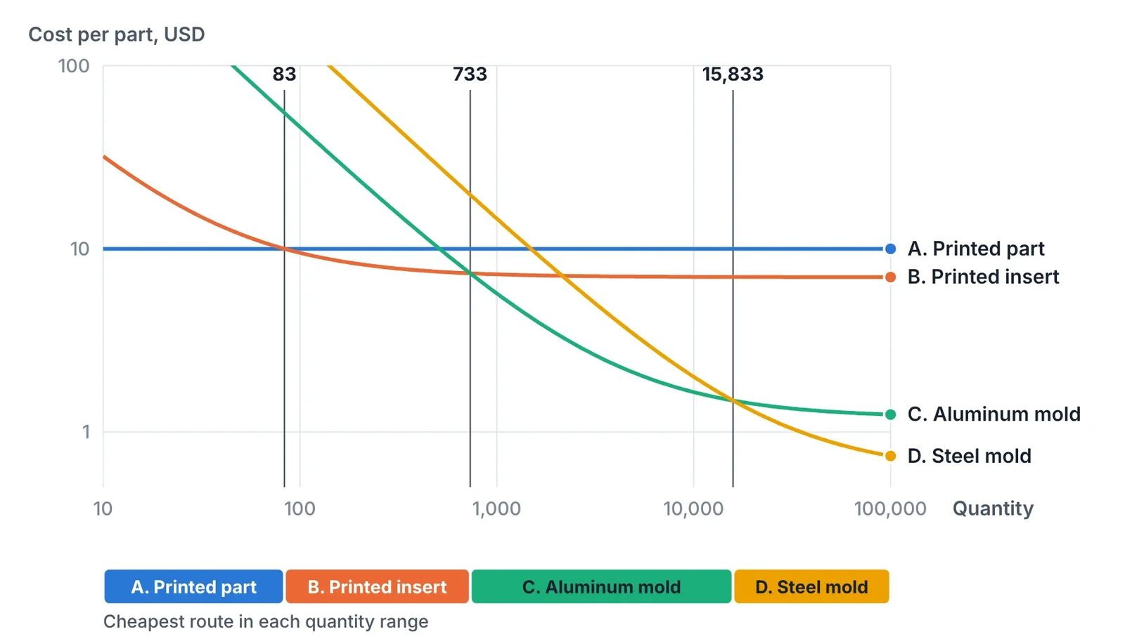
- A to B: 250 / (10.00 − 7.00) = 83 parts
- B to C: (4,500 − 250) / (7.00 − 1.20) = 733 parts
- C to D: (14,000 − 4,500) / (1.20 − 0.60) = 15,833 parts
| Quantity | A. Printed part | B. Printed insert | C. Aluminum mold | D. Steel mold |
|---|---|---|---|---|
| 50 | 10.00 | 12.00 | 91.20 | 280.60 |
| 300 | 10.00 | 7.83 | 16.20 | 47.27 |
| 1,000 | 10.00 | 7.25 | 5.70 | 14.60 |
| 5,000 | 10.00 | 7.05 | 2.10 | 3.40 |
| 50,000 | 10.00 | 7.00 | 1.29 | 0.88 |
Cost per part in USD. The lowest value in each row is in bold.
Three points limit how far the numbers can be trusted.
- Route B moves in steps. Each insert set lasts about 100 parts in this example. An order of 110 parts needs a second set for the last ten, and for that quantity direct printing is cheaper again. Order in multiples of the insert life.
- Tool life caps route C. An aluminum mold lasts roughly 1,000 to 10,000 shots depending on the plastic. If the total demand exceeds its life, steel becomes the right choice before the calculated break-even.
- Part size shifts everything. Printing cost rises with part volume, molding cost hardly does. Small parts favour printing up to higher quantities; large parts favour tooling earlier.
What the cost model leaves out
| Factor | Favours printing the part | Favours tooling |
|---|---|---|
| Design stability | Design still changing | Design frozen |
| Material | Nylon is acceptable | Specific plastic, colour, transparency or certification needed |
| Surface | Grainy surface acceptable or finishing planned | Molded gloss or texture required |
| Geometry | Undercuts, internal channels, no draft | Moldable shape with draft |
| Demand forecast | Uncertain | Confirmed |
| Time to first parts | Days matter | Weeks are available |
Route B is rarely chosen on cost alone. It is chosen when the parts must be in the production plastic and the quantity or the design does not yet justify aluminum. The method is described in the article 3D Printed Mold Inserts for Short-Run Injection Molding.
Metal parts
The same logic applies to metal parts, with different routes.
| Route | Typical quantity | Strength | Limit |
|---|---|---|---|
| CNC machining from billet | 1–100 | Any alloy, full properties, tight tolerance | Cost per part falls little with quantity |
| Direct metal printing (powder bed) | 1–100 | Complex shapes, internal passages | High cost per cm³, machining of fits still needed |
| Sand casting in printed sand molds | 5–200 | No pattern, casting alloy, large parts possible | Rough surface, machining needed |
| Investment casting from printed patterns | 10–500 | Good surface and detail, no wax tool | Pattern cost repeats with every part |
| Sand or gravity casting with conventional patterns or dies | 200–10,000 | Low piece cost | Pattern or die cost and lead time |
| High-pressure die casting | Above 5,000–10,000 | Lowest piece cost, thin walls | Die cost and lead time |
A warning applies to prototypes for die cast parts. A machined, printed or sand cast prototype has a different alloy, a different cooling rate and different porosity from a die casting. It proves fit and function. It does not prove the strength, leak tightness or dimensional behaviour of the production casting. Those depend on the die and process, as described in Porosity in Die Casting: Gas vs. Shrinkage, Causes and Fixes.
Sheet metal parts
For small batches of formed sheet parts, the blank is laser cut and only the forming tool is needed. That tool can be printed.
- Process and material. Filament printing in fibre-filled nylon or polycarbonate, with thick walls and dense infill. The tool is loaded in compression, where printed polymer is strong.
- Range. Aluminum and mild steel up to about 1.5–2 mm, in batches from ten to a few hundred parts.
- Radii. Use larger die radii than in steel tooling. Radii wear first. For longer runs, fit steel inserts at draw radii.
- Springback. A corrected die is reprinted overnight, which makes springback compensation by trial practical. The method is in Springback in Bending: Prediction and Compensation.
- Limit. Polymer does not hold a cutting edge. Blanking and piercing stay with laser cutting or steel tooling.
Choosing the route
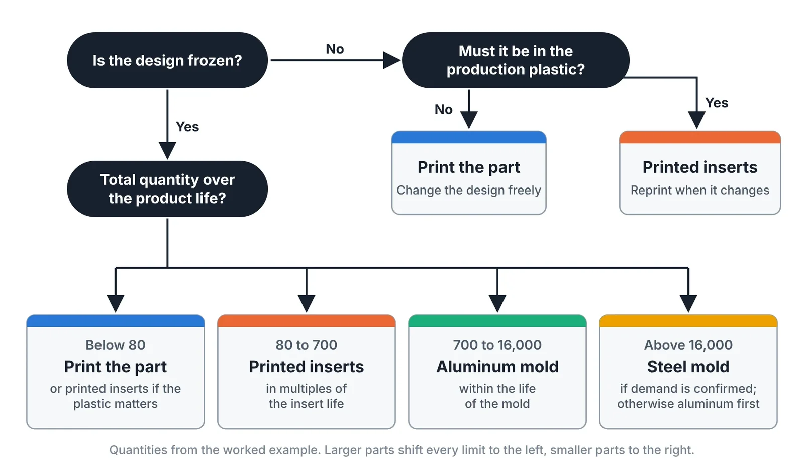
- Is the design frozen? If not, do not cut metal. Print parts or print inserts.
- Must the part be in the production material? If yes, direct printing is out and the choice is between printed inserts, aluminum and steel.
- What is the total quantity over the product life? Compare it with the break-even quantities calculated from real quotations.
- Is the demand confirmed? If it is only a forecast, choose the route with the lower fixed cost and accept a higher piece price.
- How soon are the first parts needed? Lead time can override cost for a launch or a customer approval.
The staged strategy
The three routes are not alternatives over the life of a product. They are stages.
| Stage | Quantity | Route | Purpose |
|---|---|---|---|
| Development | 1–50 | Printed parts | Fit, function, design iterations |
| Validation | 20–200 | Printed inserts | Tests in the production material |
| Launch | 500–5,000 | Aluminum mold | First sales, process learning |
| Production | Above 10,000 | Steel mold | Lowest piece cost |
Each stage reduces the risk of the next and is paid for by the parts it delivers. The steel mold is ordered when the design and the demand are both proven. Its price is built up as shown in How to Estimate the Cost of a Mold or Die.
Common mistakes
| Mistake | Result | Correct approach |
|---|---|---|
| Comparing piece prices without the tool cost | Wrong route for the quantity | Compare total cost at the expected quantity |
| Cutting a steel mold on a forecast | Expensive changes or an idle mold | Bridge with printed parts or an aluminum mold |
| Printing thousands of parts because no tool is needed | High total cost | Recalculate the break-even as demand grows |
| Approving a design on printed nylon parts only | Surprises in the molded material | Validate in the production plastic before steel |
| Ignoring tool life in the comparison | Second tool not budgeted | Include insert and mold life in the fixed cost |
Key takeaways
- Each route is cheapest over one quantity range. The break-even is the difference in fixed cost divided by the difference in cost per part.
- In the example, direct printing wins below about 80 parts, printed inserts up to about 700, an aluminum mold up to about 16,000 and steel above that.
- Cost is not the only criterion. Design stability, material, surface and certainty of demand often decide.
- Use the routes as stages: print parts in development, print inserts for validation, aluminum for launch and steel for confirmed production.
Related Articles
3D Printed Mold Inserts for Short-Run Injection Molding
How to design and run 3D printed polymer mold inserts for 10 to 100 molded parts: materials, draft, gates, process settings, insert life and failure modes.
Additive Manufacturing for Toolmakers: Processes, Materials and Where Each Fits
The additive manufacturing processes that matter in a tool shop: what each one makes, its accuracy and materials, and which mold and die jobs it suits.
Repairing Molds and Dies with Laser Cladding and Directed Energy Deposition
Mold and die repair by TIG, laser welding and laser cladding compared: heat-affected zone, dilution, filler choice, repair procedure and when to replace.
Printing Tool Steel: Maraging, H13 and What Happens After the Build
Printable tool steels compared, with the full post-processing route: stress relief, age hardening, machining allowance, polishing limits and surface treatment.
Conformal Cooling in Injection Molds and Die Casting Inserts: Design Rules and Payback
Design rules for conformal cooling channels in printed mold inserts: diameter, pitch, distance to cavity, flow, hybrid inserts, HPDC limits and payback.