
Porosity in Die Casting: Gas vs. Shrinkage, Causes and Fixes
-
 Mohamed Aboelfotouh
- Sector : Die Casting
- Oct. 2, 2026, 4:04 p.m.
Porosity is the most common reason die castings are rejected for leaks, weak sections or holes opened by machining. There are two different kinds, with different causes and opposite fixes. Adding pressure will not remove trapped air, and better venting will not feed a thick boss. The first job is always to identify which kind you have.
Step 1: Identify the type
Cut the casting through the defect area, or use X-ray, and look at the shape of the cavities and where they sit.
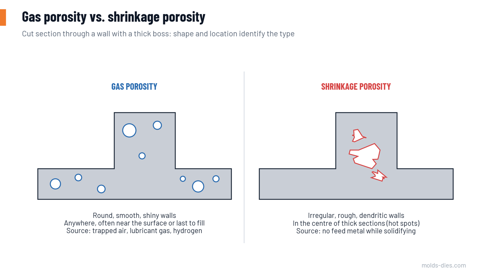
| Feature | Gas porosity | Shrinkage porosity |
|---|---|---|
| Shape | Round or oval | Irregular, branched, jagged |
| Inner surface | Smooth, often shiny | Rough, dendritic, dull |
| Typical location | Anywhere; near the surface, at the end of fill, under the gate area | Centre of thick sections, bosses, junctions of ribs and walls |
| Position from shot to shot | Moves around | Always in the same place |
| Appears after | Machining, or as blisters after heat treatment or painting | Machining into the thick section, or pressure testing |
| Reacts to | Venting, shot profile, lubricant amount | Intensification pressure, local cooling, design |
In practice both kinds often appear together: a shrinkage cavity that started on a gas pore is partly round and partly jagged. Treat the gas source first, because gas pores also weaken the feeding of shrinkage.
Gas porosity: where the gas comes from
There are three sources. Rank them before changing anything.
1. Air trapped during the shot. This is the largest source in most dies. Air in the shot sleeve, runner and cavity must leave through the vents before the metal closes them. It is trapped when:
- the sleeve is less than about 40 % full and the slow shot creates a wave that rolls over and folds air into the metal;
- the slow-shot speed is too high or too low for the fill ratio;
- the change to fast shot comes before the metal has reached the gate, so the runner is still full of air;
- vents are too small, blocked with flash or lubricant residue, or closed by the first metal to arrive;
- the runner has enlargements or sharp bends where the stream separates.
2. Gas from die and plunger lubricant. Water that has not evaporated before the die closes turns into steam. Excess plunger lubricant burns in the sleeve. Signs: porosity gets worse after a long spray, on the first shots after a stop, or on the side where the spray nozzles point.
3. Hydrogen from the melt. Less important in high-pressure die casting than in gravity casting, because solidification is fast, but it adds to the total. Wet returns, wet tools and long holding at high temperature raise it.
Fixes for gas porosity
| Cause | Action |
|---|---|
| Low sleeve fill | Smaller plunger or shorter sleeve; aim for 40–60 % fill |
| Wrong slow shot | Set slow-shot speed so one wave travels ahead of the plunger and pushes the air to the gate; typically 0.2–0.6 m/s depending on fill ratio and diameter |
| Early fast-shot start | Move the switch point to when metal is at the gate |
| Blocked vents | Clean vents every shift; check that flash is not sealing the parting face |
| Too little vent area | Add vents at the last points to fill; add chill vents or vacuum |
| Poor overflow position | Put overflows where the flow fronts end, not where there is space |
| Too much spray | Reduce volume, improve atomization, add blow-off time |
| Too much plunger lubricant | Reduce to the minimum that prevents sticking |
| Wet charge material | Dry returns; degas the melt and keep holding temperature moderate |
Shrinkage porosity: why it forms
Aluminum alloys shrink by roughly 4–7 % in volume when they solidify. Thin walls freeze first. A thick section that is still liquid then has to be fed through the walls around it, and through the gate, by the intensification pressure. Once the gate or a thin wall on the feed path has frozen, the remaining liquid in the thick section shrinks with nothing to replace it, and a cavity opens in its centre.
So shrinkage porosity depends on four things:
- how thick the section is compared with the walls that feed it;
- how long the feed path stays open (gate thickness, biscuit thickness, die temperature along the path);
- how much pressure is applied and how quickly it builds up;
- how hot the die is at the thick section.
Fixes for shrinkage porosity
| Lever | Action | Typical values |
|---|---|---|
| Intensification pressure | Raise metal pressure in the third phase | 400 bar for standard parts, 600 bar for loaded parts, 800–1,000 bar for pressure-tight parts |
| Pressure build-up time | Shorten the delay between end of fill and full pressure | A few tens of milliseconds; a slow build-up acts on metal that is already frozen |
| Biscuit thickness | Keep it thick enough to transmit pressure | About 15–30 mm; a thin biscuit freezes and the plunger stops feeding |
| Gate thickness | Thicker gate near thick sections | Feed path must freeze after the section it feeds |
| Gate position | Feed thick sections first, from the gate side | Avoid feeding a boss through a long thin wall |
| Local cooling | Spot cooling (jet coolers, cooled core pins) in bosses | Brings the hot spot closer to the wall freezing time |
| Local squeeze | Squeeze pin acting on the hot spot after fill | Used when design cannot change |
| Part design | Core out bosses, replace mass with ribs, uniform walls | Most effective and cheapest if done before the die is built |
Be careful with higher intensification pressure: it increases the opening force on the die. Check the locking force before raising it, or the result is flash and a casting that is thicker but no denser.
A diagnostic sequence that saves time
- Section or X-ray three castings from the same cavity and mark the pore positions. Same place every time means shrinkage. Wandering means gas.
- Read the shot curve. Check the switch point to fast shot, the fast-shot speed actually reached, the pressure build-up time and the final pressure. Compare them with the values on the process sheet.
- Measure the biscuit. Variation in biscuit thickness means variation in metal dose, which changes the switch point and the pressure transmission.
- Inspect the die face. Look at vents, overflow gates and flash marks before touching machine settings.
- Change one thing, run enough shots for the die to reach thermal balance again, and section again.
How to measure and specify porosity
| Method | What it shows | Use |
|---|---|---|
| Sectioning and visual check | Shape, size, exact position | Diagnosis; destructive |
| X-ray or CT | Size and position without cutting | Process approval, audit, safety parts |
| Density comparison (weighing in air and water) | Overall porosity level of a casting or a cut-out piece | Quick process monitoring |
| Pressure or leak test | Whether pores connect to the surface | 100 % check on pressure-tight parts |
On the drawing, define zones. Ask for low porosity only where it matters: sealing faces, machined bores, threaded bosses and highly loaded sections. A general requirement for "no porosity" cannot be met by this process and makes every casting a discussion. Reference radiograph standards for aluminum die castings give graded levels that both sides can agree on.
Key takeaways
- Round and smooth means gas; jagged and always in the thick section means shrinkage.
- Gas porosity is fixed on the way in: sleeve fill, slow shot, switch point, vents, overflows and the amount of lubricant.
- Shrinkage porosity is fixed by feeding: intensification pressure and timing, biscuit and gate thickness, local cooling and part design.
- Check locking force before raising the pressure, and change one variable at a time.
Related Articles
High-Pressure Die-Casting Process
Explore the high-pressure die-casting process, a method for producing metal parts with high precision and uniformity. Learn its benefits and applications
Die Life in HPDC: Heat Checking, Soldering and How to Delay Them
The main failure modes of die casting dies — heat checking, soldering, erosion and gross cracking — and the design, steel and process measures that extend die life.
Choosing a Die Casting Machine: Locking Force and Shot Size
How to calculate locking force, shot weight, plunger diameter and sleeve fill ratio to match a casting to the right cold-chamber die casting machine.
Overflows, Vents and Vacuum: Getting the Air Out of the Die
Practical rules for placing and sizing overflows, vents, chill vents and vacuum channels in high-pressure die casting dies.
HPDC Gating Design: Gate Area, Gate Velocity and Fill Time
A step-by-step method to size the gate of a high-pressure die casting die from cavity fill time and gate velocity, with a worked example and reference tables.