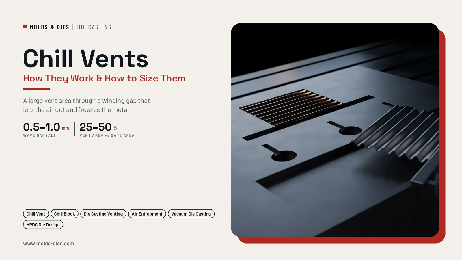
Chill Vents in Die Casting: How They Work and How to Size Them
-
 Mohamed Aboelfotouh
- Sector : Die Casting
- Oct. 16, 2026, 12:01 p.m.
Air that cannot leave the cavity during the shot ends up as porosity in the casting. Flat vents at the parting line are simple, but they must be very shallow to stop the metal, so their area is small and they block quickly. A chill vent solves this with a block of ribbed or wave-shaped steel or copper alloy that gives a large vent area along a zig-zag path. Air passes freely; metal that follows it is cooled and freezes before it reaches the end. This article explains how chill vents work, how to size and place them, and how to keep them working.
How a chill vent works
A chill vent consists of two matching blocks, one in each die half, with wave-shaped or ribbed faces. When the die closes, the waves nest into each other and leave a narrow, winding gap between them. A collector runner connects the overflows to the entry side of the block; the exit side opens to the outside of the die.
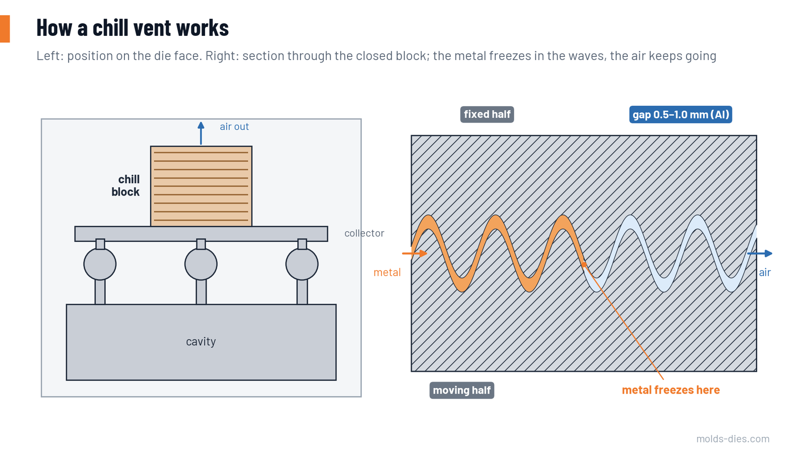
During filling, air is pushed ahead of the metal through the overflows, along the collector and out through the gap. When the metal arrives, it enters the gap and gives up heat to the large, cool surface of the waves on both sides. It freezes after a short distance, sealing the vent before it can spray out of the die.
Why not flat vents only
Flat vents are limited by depth. For aluminum they are typically 0.10–0.15 mm deep near the cavity; deeper, and metal escapes. A chill block can use a gap several times deeper because the waves freeze the metal.
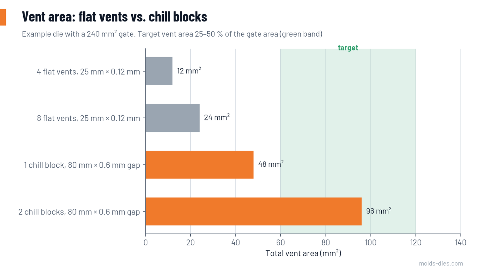
| Example die: gate area 240 mm² | Vent area | Share of gate area |
|---|---|---|
| 4 flat vents, 25 mm wide × 0.12 mm | 12 mm² | 5 % |
| 8 flat vents, 25 mm wide × 0.12 mm | 24 mm² | 10 % |
| 1 chill block, 80 mm wide × 0.6 mm gap | 48 mm² | 20 % |
| 2 chill blocks, 80 mm wide × 0.6 mm gap | 96 mm² | 40 % |
A common target is a vent area of 25–50 % of the gate area. Flat vents alone rarely reach it; one or two chill blocks do.
How much air? In the same example, the cavity and overflows hold about 0.5 litres, the runner about 0.14 litres, and the empty part of a half-filled shot sleeve about 0.7 litres. Most of the sleeve air should leave during the slow shot. But the cavity air has to leave in the fast fill time, around 50 milliseconds. That short time is why vent area matters so much.
Design rules
| Feature | Guideline for aluminum |
|---|---|
| Gap between the waves | 0.5–1.0 mm, often 0.6–0.8 mm; magnesium similar; zinc smaller |
| Width of the block | 40–150 mm, as the die layout allows |
| Wave pitch and height | A few millimetres each; several full waves along the flow path so the metal turns repeatedly |
| Path length | Long enough that the metal freezes inside the block; check that the first shots on a warm die do not spit |
| Entry from the collector | Collector runner as wide as the block entry, slightly thicker than the vent gap, so air is not throttled before the block |
| Exit | Open to the outside of the die, pointing away from the operator side, preferably at the top of the die |
| Block material | Hot-work steel, hardened and nitrided; or a high-conductivity copper alloy for stronger chilling where the shot volume of air is large |
| Block cooling | Water channels in or behind the block; a hot block lets metal travel further |
| Matching | The two halves must align so the gap is even everywhere; locate with dowels or keys |
| Replaceability | Fit as inserts so a worn or damaged block can be changed without reworking the die |
Locking force. The chill block and its collector fill with metal and add to the projected area. Include them when calculating the opening force.
Where to put the chill vent
- At the end of fill. The block must connect to the overflows at the last points to fill. A chill vent next to the gate vents nothing useful.
- After overflows, not instead of them. The overflows collect the cold, dirty first metal; the chill block takes only the air and the last bit of metal.
- At the top of the die where possible. Air collects high in a vertical die, and the exit is away from the floor and the operator.
- Several overflows to one block. A collector runner joins the overflows along one side of the cavity, so one block serves a long edge.
- Away from ejector pins and slides that need access to the same area.
Chill vents and vacuum
A chill block can also be the shut-off element of a vacuum system. The vacuum line is connected to the exit side. Air is drawn out through the open gap before and during filling, and the metal seals the block by freezing in the waves. This avoids a mechanical vacuum valve and its timing, at the cost of a smaller flow area than a large valve. It suits small and medium castings with moderate vacuum requirements.
Maintenance
| Check | Frequency | Action |
|---|---|---|
| Aluminum left in the waves | Every shift | Remove the frozen vent piece with the casting; clean residue with brass tools |
| Gap closing from build-up | Every die service | Clean, polish and re-nitride the waves |
| Gap opening from wear or erosion | Every die service | Measure with feelers or a lead impression; replace inserts if the gap is above the limit |
| Cooling | Every die service | Flow test the block cooling |
| Cracks at the wave roots | Major service | Dye-penetrant check; replace the insert |
Signs that a chill vent is not doing its job:
| Symptom | Likely cause | Correction |
|---|---|---|
| Metal spits out of the vent | Gap too large, block too hot, or block worn | Check gap and cooling; reduce intensification only if needed |
| Porosity at the end of fill unchanged | Vent not connected to the real last-fill point, or blocked | Check the flow pattern with short shots; clean the block |
| Vent piece breaks and stays in the die | Thin, brittle frozen wafer; soldering in the waves | Polish and coat the waves; check draft and ejection of the vent piece |
| Flash around the block | Blocks not seated flush, or locking force too low | Check seating and the projected area in the force calculation |
Common mistakes
| Mistake | Result |
|---|---|
| Chill block placed where there was space, not at the last fill | Air remains trapped; block fills early |
| Collector thinner than the vent gap | Air throttled before it reaches the block |
| Uncooled block in a high-volume die | Block heats up; metal spits after some hours |
| Gap increased to "vent more" | Metal escapes; safety risk |
| Block projected area left out of the force check | Flash at the chill vent |
| No spare inserts | Long stoppage when a block cracks |
Key takeaways
- A chill vent gives a large vent area through a winding gap that lets air out and freezes the metal.
- For aluminum use a gap of about 0.5–1.0 mm, a width of 40–150 mm, several waves, and a cooled block.
- Aim for a total vent area of 25–50 % of the gate area; one or two chill blocks usually reach it where flat vents cannot.
- Connect the block to the overflows at the end of fill, include it in the locking-force check, and clean and measure it at every die service.
Share Article
Related Articles