
Overflows, Vents and Vacuum: Getting the Air Out of the Die
-
 Mohamed Aboelfotouh
- Sector : Die Casting
- Oct. 2, 2026, 4:05 p.m.
Before every shot, the cavity, the runner and the empty part of the shot sleeve are full of air. The metal fills the cavity in a few hundredths of a second, so that air has very little time to leave. What does not leave ends up inside the casting as gas porosity or on its surface as cold flow and blisters. Overflows, vents and vacuum are the three tools for dealing with it. This article gives the rules for placing and sizing each of them.
What each element does
| Element | Main job | Secondary jobs |
|---|---|---|
| Overflow | Receives the first metal at the end of each flow path, which is cold and carries oxides, lubricant residue and air | Heats a cold area of the die; gives a place for ejector pins; moves the last-to-fill point out of the part |
| Vent | Lets air leave the cavity and the overflows to the outside of the die | — |
| Chill vent (wave block) | A vent with a large area and a zig-zag path that freezes the metal before it reaches the outside | Can be connected to a vacuum system |
| Vacuum system | Removes most of the air before the fast shot starts | Lowers the back-pressure the metal has to fill against |
Placing overflows
The position matters more than the size. An overflow in the wrong place only adds scrap weight.
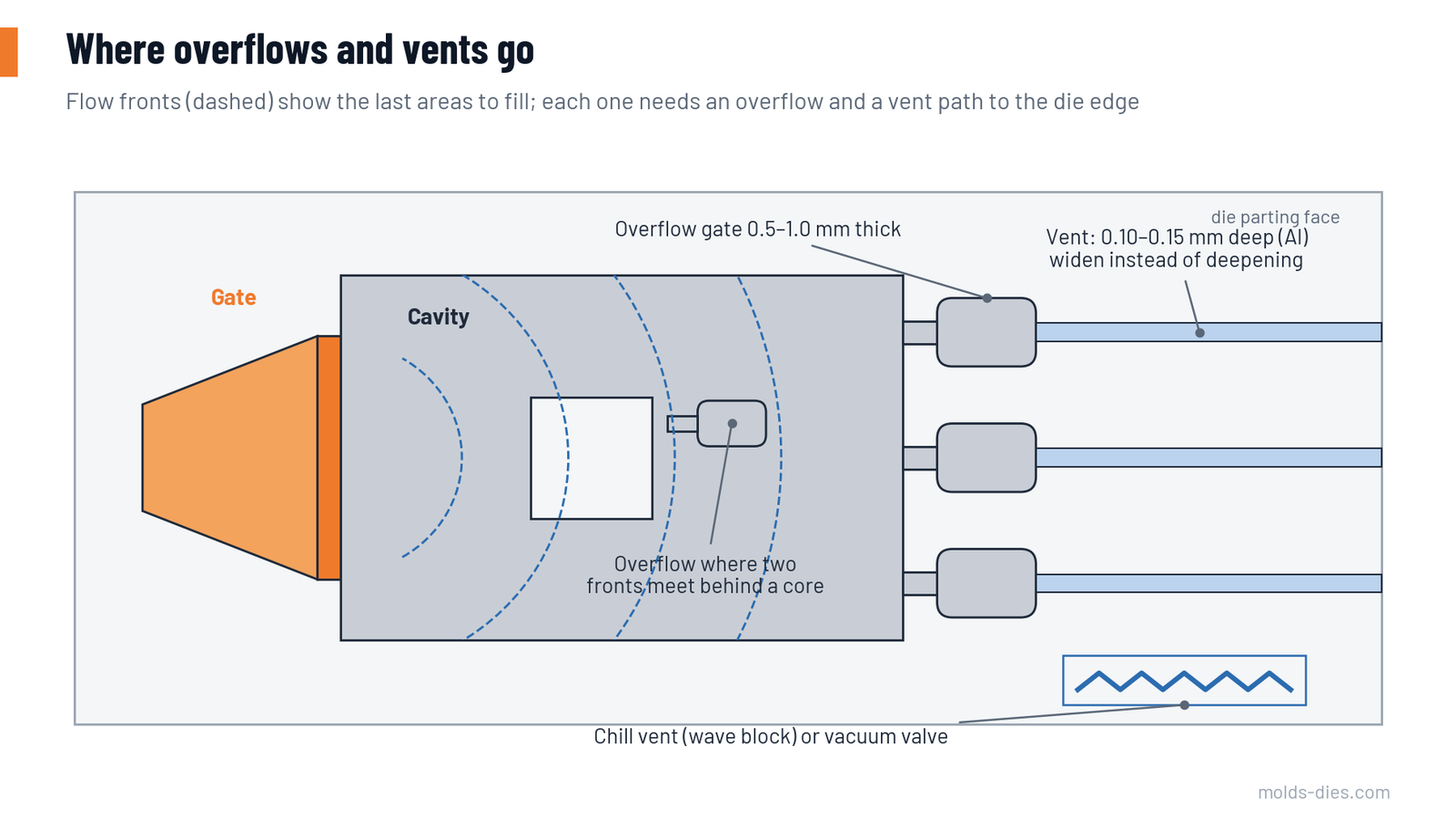
- Find the last points to fill. Use a filling simulation, or sketch the flow fronts by hand from the gate: the metal travels roughly as an expanding front, turns around cores and windows, and ends in the far corners and behind obstacles.
- Put an overflow at each end point and wherever two fronts meet, for example behind a core or a window.
- Do not put overflows close to the gate. They fill first, close their vents, and take metal and pressure away from the cavity.
- Keep the overflow gate in line with the flow, so the dirty first metal runs straight in instead of turning.
- Use overflows to balance die temperature in thin, distant areas that run cold, and to carry ejector pins where pin marks on the part are not allowed.
Sizing overflows
Thin walls need relatively more overflow volume, because the first metal has lost more of its heat by the time it arrives. The table gives a workable starting point, expressed as a share of the volume of the cavity segment the overflow serves.
| Wall thickness of the segment (mm) | Overflow volume, normal surface | Overflow volume, high surface quality |
|---|---|---|
| About 1.0 | 75–100 % | up to 150 % |
| 1.5 | 50 % | 100 % |
| 2.0 | 25–50 % | 50 % |
| 2.5–3.0 | 25 % | 25–50 % |
| Above 3.0 | 10–25 % | 25 % |
Further sizing rules:
- Overflow gate thickness: 0.5–1.0 mm for aluminum, thinner than the main gate so it breaks off cleanly and freezes before intensification.
- Overflow gate width: as wide as the overflow allows; several small overflows work better than one large one.
- Overflow depth: usually 6–12 mm with generous draft (10° or more) and an ejector pin under each one.
- Total overflow gate area: roughly half to all of the main gate area in dies with thin walls.
Sizing vents
A vent must be deep enough to pass air and shallow enough to freeze the metal that follows the air.
| Alloy | Vent depth near the cavity (mm) | Vent depth beyond 20–30 mm from the cavity (mm) |
|---|---|---|
| Aluminum | 0.10–0.15 | up to 0.20–0.25 |
| Magnesium | 0.10–0.15 | up to 0.20 |
| Zinc | 0.05–0.10 | up to 0.15 |
- Width: 10–30 mm per vent. If more area is needed, add width or more vents. Never add depth near the cavity: a deep vent spits metal out of the die.
- Total vent area: as a target, at least 25–50 % of the gate area.
- Path: every vent must reach the outside edge of the die block. A vent that ends in the middle of the parting face vents nothing.
- Change direction once on the way out, so a metal jet cannot shoot straight out of the die toward the operator.
Why flat vents are rarely enough
Take a gate area of 240 mm². A vent area of 25 % is 60 mm². At 0.12 mm depth, that needs 500 mm of total vent width, for example 20 vents of 25 mm each. Few dies have room for that, and flat vents lose area quickly as flash and lubricant build up. This is the reason for chill vents and vacuum.
Chill vents
A chill vent is a pair of ribbed steel or copper-alloy blocks at the end of a collecting channel. The gap between the ribs is typically 0.5–1.0 mm and the width 60–150 mm, so one block gives 30–150 mm² of vent area. The zig-zag path and the large cooled surface freeze the metal before it reaches the end.
Rules for using them:
- connect several overflows to one chill vent through a collector runner;
- place the block at the top of the die or on the side away from the operator;
- cool the block, and check its projected area in the locking force calculation;
- clean it at every die service, because a block coated with aluminum has lost its gap.
Vacuum: when it pays
Vacuum removes most of the air instead of pushing it out. It is justified when the castings must be pressure-tight, welded, heat treated to T6 without blistering, or when thin walls far from the gate cannot be filled soundly in any other way.
| Conventional venting | Vacuum-assisted | High vacuum | |
|---|---|---|---|
| Cavity pressure at fast-shot start | about 1,000 mbar | 100–300 mbar | below 50–80 mbar |
| Die sealing | none | basic: parting face, vents through the valve only | full: parting face, ejector pins, slides, sleeve and plunger |
| Typical castings | general purpose | pressure-tight and thin-wall parts | structural, weldable, heat-treatable parts |
| Extra cost and care | low | valve, tank, filters, daily cleaning | sealed die design, monitored vacuum level every shot |
Points that decide whether a vacuum system works:
- Timing. Evacuation starts after the plunger has passed and closed the pour hole, and must be finished before the fast shot. That gives roughly one second. The channel cross-section and the tank volume must suit that time.
- Leaks. A die that leaks air through the ejector pins or the sleeve never reaches a useful vacuum. Measure the level reached in the cavity, not the level in the tank.
- Valve protection. The valve must close before the metal reaches it. Use a chill block or a mechanically operated valve ahead of it.
- Lubricant. Less spray and less plunger lubricant are needed, since vacuum also draws lubricant vapour into the filters.
Vacuum does not replace overflows. They are still needed to take the cold, oxidized first metal.
Maintenance checklist
| Interval | Check |
|---|---|
| Every shift | Vents and overflow gates free of flash and residue; parting face clean; chill vent gap open |
| Every die service | Measure vent depth at three points; re-grind worn vents; replace vacuum seals; clean valve and filter |
| After any gate change | Re-check that overflows are still at the end of the flow paths |
Key takeaways
- Put overflows at the ends of the flow paths and where fronts meet; position matters more than size.
- Vents are shallow by necessity: 0.10–0.15 mm for aluminum. Add area with width, chill vents or vacuum, not depth.
- Aim for a vent area of at least a quarter of the gate area and check how close the die really comes to it.
- Vacuum only works with a sealed die, correct timing and a measured cavity pressure.
Related Articles
Die Life in HPDC: Heat Checking, Soldering and How to Delay Them
The main failure modes of die casting dies — heat checking, soldering, erosion and gross cracking — and the design, steel and process measures that extend die life.
Choosing a Die Casting Machine: Locking Force and Shot Size
How to calculate locking force, shot weight, plunger diameter and sleeve fill ratio to match a casting to the right cold-chamber die casting machine.
Porosity in Die Casting: Gas vs. Shrinkage, Causes and Fixes
How to tell gas porosity from shrinkage porosity in die castings, what causes each one, and the process and die changes that actually reduce them.
HPDC Gating Design: Gate Area, Gate Velocity and Fill Time
A step-by-step method to size the gate of a high-pressure die casting die from cavity fill time and gate velocity, with a worked example and reference tables.
High-Pressure Die-Casting Process
Explore the high-pressure die-casting process, a method for producing metal parts with high precision and uniformity. Learn its benefits and applications