Jet Cooling in Die Casting Dies: Sizing, Water Supply and Control
-
 Mohamed Aboelfotouh
- Sector : Die Casting
- Oct. 16, 2026, 11:54 a.m.
Some areas of a die-casting die cannot be reached by normal cooling channels: slender core pins, thin cores between ribs, bosses deep inside the casting. These areas run hottest in the die, and they cause shrinkage porosity in the casting next to them, soldering on the steel, and long cycle times. Jet cooling, also called spot cooling or high-pressure point cooling, brings water to the tip of these features through a small blind bore. This article explains how it works, how to size it, and how to run it without cracking the die.
How jet cooling works
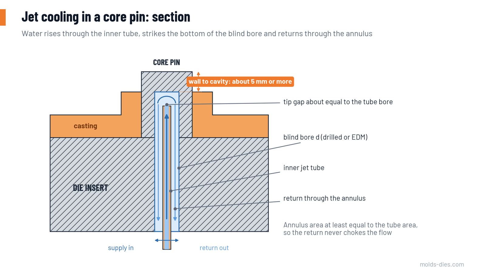
A blind hole is drilled or eroded into the core pin or insert from the back, ending a few millimetres below the cavity surface. A thin tube sits in the middle of the hole. Water is supplied through the tube at high pressure, strikes the bottom of the bore, and returns through the ring-shaped space (annulus) between tube and bore wall.
Two things make it effective:
- The water reaches the hot spot directly. The heat path through the steel is a few millimetres instead of tens.
- The water is fast and under pressure. High velocity breaks the boundary layer at the hot bore bottom, and high pressure raises the boiling point, so the water does not form an insulating steam film.
Where to use it
| Feature | Why it needs jet cooling | Typical benefit |
|---|---|---|
| Core pins for bores and threads | Surrounded by metal; no room for channels | Less soldering, fewer pin breakages, more accurate bores |
| Thin cores between ribs | Heated from both sides | Less shrinkage porosity in the ribs, less washout |
| Bosses and thick local sections | Last area of the casting to solidify | Shrinkage porosity moved or removed |
| Areas opposite the gate | Hit by the hottest, fastest metal | Less soldering and erosion |
| Slides with deep cores | Far from the main cooling | More stable slide temperature |
Use it only where it is needed. Each jet is a drilled hole close to the cavity surface, a potential leak point and an extra item to maintain.
Sizing rules
| Core pin or feature diameter | Blind bore diameter | Jet tube outer / inner diameter | Notes |
|---|---|---|---|
| 6–10 mm | 3 mm | 1.5 / 1.0 mm | Smallest practical size; filtration is critical |
| 10–16 mm | 4–5 mm | 2.5–3 / 1.8–2 mm | Most common range |
| 16–25 mm | 6–8 mm | 4 / 3 mm | |
| Above about 25 mm | — | — | A conventional bubbler or baffle usually has room |
Further rules:
- Wall to the cavity surface. Keep about 5 mm or more of steel between the bottom of the bore and the cavity surface as a guide, more on larger cores and on high-pressure castings. A thinner wall cools better but cracks through sooner, and a crack here means water in the cavity.
- Tip gap. The tube should end at a distance from the bore bottom roughly equal to its own inner diameter. Too close restricts the flow; too far lets the jet lose its speed.
- Return area. The annulus area must be at least equal to the tube's inner area. Example: a 5 mm bore with a 3 mm tube has an annulus of 12.6 mm²; a tube bore of 2 mm has 3.1 mm². The return is four times larger, which is correct.
- Bore bottom shape. Avoid a sharp drill point that concentrates stress. A rounded or flat bottom, made by EDM or a ball-end tool, is preferred.
- Straight, centred tube. The tube must be held concentric so the annulus is even all round; a tube touching one side leaves that side uncooled.
- Sealing. Seal the tube holder and bore entry with suitable O-rings or threaded seals rated for the temperature at the back of the die.
Water supply
| Parameter | Typical value | Reason |
|---|---|---|
| Supply pressure | About 8–15 bar | Keeps water liquid at the hot bore bottom and drives flow through small tubes |
| Flow per jet | 0.5–3 litres per minute | Depends on tube size and heat load |
| Water temperature | 20–40 °C | Consistent, not chilled; very cold water increases thermal shock |
| Water quality | Softened or demineralized, with corrosion inhibitor | Scale closes small bores within weeks if hard water is used |
| Filtration | Fine filter in the supply, typically in the range of 25–100 µm | Particles block 1 mm passages |
Worked example
A 14 mm core pin forms a boss of about 50 g of aluminum. The cycle time is 60 seconds.
| Quantity | Calculation | Result |
|---|---|---|
| Heat released by the boss metal per shot, from pouring temperature to ejection (about 770 kJ/kg including the latent heat) | 0.05 kg × 770 kJ/kg | about 38 kJ |
| Average heat load | 38 kJ ÷ 60 s | about 0.64 kW |
| Water flow for a 10 °C temperature rise | 0.64 ÷ (4.18 × 10) | 0.015 kg/s, about 0.9 L/min |
| Chosen jet | 5 mm bore, 3 / 2 mm tube, 1–1.5 L/min | Within the typical range |
Not all of the boss heat goes into the pin, but the estimate shows the order of magnitude: a single jet removes heat in the range of half a kilowatt to a kilowatt.
How to run it: timing and control
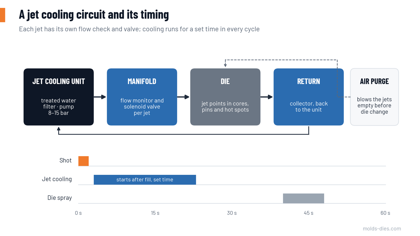
Running jets continuously is the most common mistake. It overcools the area during the die-open phase and spray, which increases the temperature swing and the heat checking that jet cooling is supposed to reduce.
| Control mode | How it works | Use |
|---|---|---|
| Continuous | Water flows all the time | Only for very hot, thick areas with mild cooling |
| Timed (pulsed) | Valve opens after metal fill, for a set number of seconds, triggered by the machine | Standard method; repeatable heat removal per shot |
| Temperature-controlled | A thermocouple near the jet switches the valve | Best stability; more sensors to maintain |
Rules for operation:
- Do not start jets on a cold die. Preheat first, then switch on jet cooling after the first shots, once the die is near working temperature.
- Start cooling after fill, during solidification. Set the duration so the bore return water is warm but not boiling.
- Monitor flow on every jet. A blocked jet looks normal from outside. Flow monitors with an alarm per circuit catch it before porosity or soldering returns.
- Purge with air at the end of production and before the die leaves the machine, so no water stands in the bores to corrode them or freeze.
- Stop at once on a leak alarm. Water in the cavity of a die-casting die can cause a steam explosion when metal is injected.
Maintenance
| Interval | Task |
|---|---|
| Every die service | Flow test each jet; check that return water is clear |
| Every major service | Remove tubes, inspect and descale bores; check bore bottom for cracks with dye penetrant; replace seals |
| When heat checking is found at a jet area | Measure remaining wall thickness; plan an insert change before the crack reaches the bore |
| Water system | Check filter, water hardness and inhibitor level on a fixed schedule |
Common mistakes
| Mistake | Result |
|---|---|
| Hard, unfiltered water | Bores scale up; cooling fades over weeks |
| Continuous cooling from a cold start | Thermal shock; early cracks at the bore bottom |
| Wall too thin to "cool better" | Crack through to the cavity; water leak |
| Return annulus smaller than the tube | Low flow, boiling at the tip |
| No flow monitoring | Blocked jets go unnoticed |
| Jets added without changing the process | Porosity moves instead of disappearing |
Key takeaways
- Jet cooling brings high-pressure water through a tube to the bottom of a blind bore in core pins and hot spots that normal channels cannot reach.
- Size the bore, tube and wall together: keep about 5 mm of wall, a tip gap near the tube bore, and a return area at least equal to the supply.
- Use treated, filtered water at about 8–15 bar, and run the jets on a timed cycle after fill rather than continuously.
- Monitor flow on every jet, purge with air after use, and inspect the bore bottoms at each major service.
Share Article
Related Articles