
HPDC Gating Design: Gate Area, Gate Velocity and Fill Time
-
 Mohamed Aboelfotouh
- Sector : Die Casting
- Oct. 2, 2026, 4:01 p.m.
The gate is the smallest section in the whole feeding system of a die casting die, and it controls two things at once: how long the cavity takes to fill and how fast the metal enters it. If the gate is too small, the machine cannot deliver the flow and the casting shows cold shuts. If it is too large, the metal enters slowly, does not atomize, and traps air in large pockets. This article gives a calculation sequence you can follow for any aluminum, zinc or magnesium casting, with a worked example at the end.
The sequence in short
- Choose the cavity fill time from the wall thickness.
- Choose the gate velocity from the alloy and the quality requirement.
- Calculate the flow rate and the gate area.
- Split the gate area into thickness and length.
- Size the runner back from the gate.
- Check that the machine can deliver the flow.
Step 1: Choose the cavity fill time
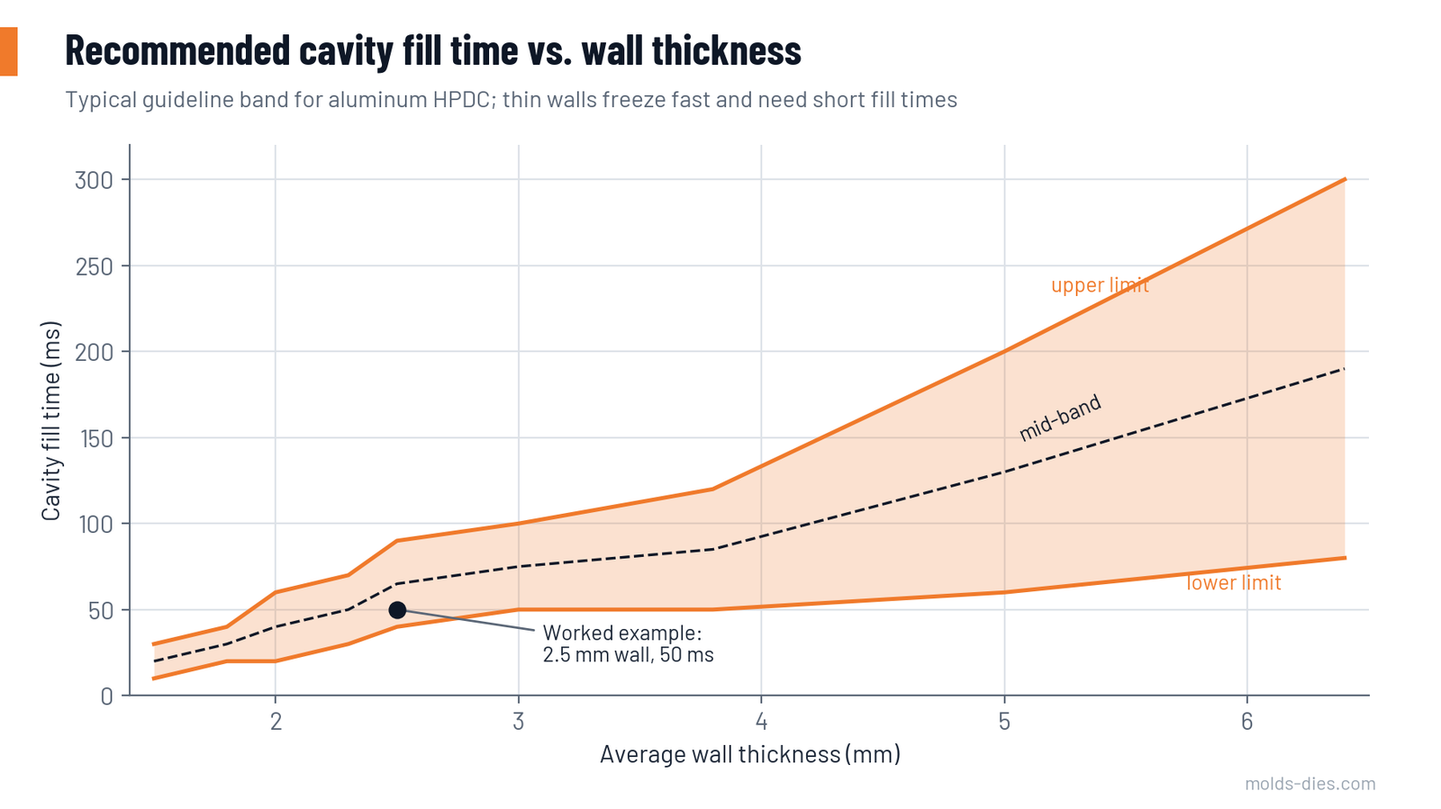
Fill time is the time from the moment metal reaches the gate until the cavity and its overflows are full. It must be shorter than the time the thinnest wall needs to start freezing, otherwise two metal fronts meet half solid and leave a cold shut.
The table gives the commonly used guideline band for aluminum. Thin walls need short fill times. Long flow distances, a cold die or a high surface-finish requirement push the choice toward the lower end of the band.
| Average wall thickness (mm) | Fill time (ms) |
|---|---|
| 1.5 | 10–30 |
| 2.0 | 20–60 |
| 2.5 | 40–90 |
| 3.0 | 50–100 |
| 3.8 | 50–120 |
| 5.0 | 60–200 |
| 6.4 | 80–300 |
Use the thinnest wall that covers a significant area, not the nominal wall on the drawing. A casting that is 3 mm in general but has a large 1.8 mm cover area should be treated as a 1.8–2.0 mm casting.
Step 2: Choose the gate velocity
Gate velocity decides the flow pattern. Above a certain speed the metal breaks into a fine spray (atomized flow), which fills thin sections well and distributes the trapped air as very small pores. Too high a speed erodes the die steel in front of the gate and promotes soldering.
| Alloy | Usual range (m/s) | Common starting value (m/s) |
|---|---|---|
| Aluminum | 30–60 | 40–45 |
| Magnesium | 40–90 | 50–60 |
| Zinc | 30–50 | 40 |
| Brass | 20–40 | 30 |
Choose toward the upper end for thin walls and cosmetic surfaces. Choose toward the lower end for thick, pressure-tight parts where the gate is thick and you want the intensification pressure to act through it for as long as possible. For aluminum, treat 60 m/s as the limit for die life.
Step 3: Calculate the flow rate and the gate area
First find the volume that passes through the gate: the casting plus its overflows. The runner and biscuit do not pass through the gate, so leave them out.
- Volume V = mass through the gate ÷ liquid density
- Flow rate Q = V ÷ fill time
- Gate area A = Q ÷ gate velocity
Use the liquid density, not the solid density: about 2.5 g/cm³ for aluminum alloys, 6.1 g/cm³ for zinc alloys and 1.65 g/cm³ for magnesium alloys.
Step 4: Split the area into thickness and length
Gate area is thickness × total gate length. The two are not interchangeable:
- Thickness decides atomization, freezing and trimming. A thin gate atomizes well and breaks off cleanly, but it freezes early and cuts off the intensification pressure. For aluminum walls of 2–4 mm, gate thicknesses of 1.0–2.5 mm are usual; below about 0.8 mm the gate is hard to keep consistent as the die wears.
- Length decides how the metal is spread over the cavity. A long, thin gate along one edge gives a wide, even front. Several short gates give separate jets that must be aimed so they do not collide early.
Keep the gate thinner than the wall it enters. A gate as thick as the wall leaves a break-off scar in the casting and may pull material out of the part at trimming.
Aim the flow along the longest path of the cavity, toward the overflows, and away from cores and die walls directly in front of the gate. Metal that hits steel at 40 m/s a few millimetres after the gate will wash out that steel.
Step 5: Size the runner
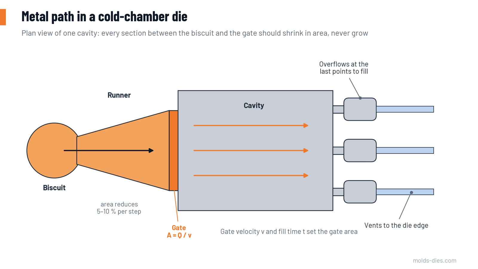
Work backward from the gate to the biscuit. The rule is that the cross-section must never increase in the direction of flow, because any enlargement lets the stream separate from the wall and mix with air.
| Section | Area relative to the gate area it feeds |
|---|---|
| Gate | 1.0 |
| Gate runner (fan or tangential) at its exit | 1.05–1.15 |
| Branch runner | 1.15–1.3 |
| Main runner at the biscuit | 1.3–1.5 |
Use a trapezoidal runner section with a width about 1.5 to 2 times its depth and 10° side draft. At every branch, the area of the incoming runner should be 5–10 % larger than the sum of the outgoing ones. Give all bends a generous radius.
Step 6: Check the machine
The flow rate must be delivered by the plunger:
- Fast-shot plunger speed = Q ÷ plunger area
If the required plunger speed is above what the machine reaches with a loaded shot end (often 4–6 m/s on the nameplate, less in practice), choose a larger plunger, a longer fill time, or a different machine. Also confirm on the machine's pressure–flow diagram that it can supply the pressure needed to push that flow through the gate.
Worked example
An aluminum housing weighs 1.0 kg. Its overflows weigh 0.2 kg. The governing wall is 2.5 mm. The machine has a 70 mm plunger.
| Quantity | Calculation | Result |
|---|---|---|
| Volume through the gate | 1,200 g ÷ 2.5 g/cm³ | 480 cm³ |
| Fill time | from the table, 2.5 mm wall | 50 ms |
| Flow rate Q | 480 ÷ 0.050 | 9,600 cm³/s (9.6 L/s) |
| Gate velocity | chosen | 40 m/s |
| Gate area | 9,600 ÷ 4,000 cm/s | 2.4 cm² = 240 mm² |
| Gate thickness | chosen | 1.5 mm |
| Gate length | 240 ÷ 1.5 | 160 mm |
| Main runner area | 1.3 × 240 | about 310 mm² |
| Plunger area | 70 mm diameter | 38.5 cm² |
| Fast-shot speed | 9,600 ÷ 38.5 | 249 cm/s = 2.5 m/s |
A 160 mm gate fits along one long side of the housing, and 2.5 m/s is well within the range of a normal cold-chamber machine, so the design is workable. If the result had been 5 m/s, the first correction would be a larger plunger, not a smaller gate.
Common mistakes
| Mistake | What happens | Correction |
|---|---|---|
| Gate sized "by experience" and opened later | Velocity unknown, die already eroded | Calculate first, then cut the gate slightly small and open it once |
| Runner larger than needed "to be safe" | Air mixed into the metal, more return scrap | Keep the area steps in the table |
| Using casting weight only | Overflows forgotten, gate too small | Include everything that passes the gate |
| Using solid density | Volume about 7 % too low | Use liquid density |
| Gate aimed at a core | Washout and soldering on the core | Redirect the flow or move the gate |
| Same gate after a plunger change | Velocity changes with plunger speed setting | Re-check the fast-shot speed |
Key takeaways
- Fill time comes from wall thickness; gate velocity comes from the alloy and the quality target. Together they fix the gate area.
- Thickness and length of the gate have different jobs: thickness for atomization and feeding, length for distributing the metal.
- The runner area must decrease steadily from biscuit to gate.
- Always finish by checking the plunger speed and the machine's pressure–flow capacity. A gate that the machine cannot feed is not a design.
Related Articles
Die Life in HPDC: Heat Checking, Soldering and How to Delay Them
The main failure modes of die casting dies — heat checking, soldering, erosion and gross cracking — and the design, steel and process measures that extend die life.
Choosing a Die Casting Machine: Locking Force and Shot Size
How to calculate locking force, shot weight, plunger diameter and sleeve fill ratio to match a casting to the right cold-chamber die casting machine.
Overflows, Vents and Vacuum: Getting the Air Out of the Die
Practical rules for placing and sizing overflows, vents, chill vents and vacuum channels in high-pressure die casting dies.
Porosity in Die Casting: Gas vs. Shrinkage, Causes and Fixes
How to tell gas porosity from shrinkage porosity in die castings, what causes each one, and the process and die changes that actually reduce them.
High-Pressure Die-Casting Process
Explore the high-pressure die-casting process, a method for producing metal parts with high precision and uniformity. Learn its benefits and applications