
Choosing a Die Casting Machine: Locking Force and Shot Size
-
 Mohamed Aboelfotouh
- Sector : Die Casting
- Oct. 2, 2026, 4:05 p.m.
A casting put on a machine that is too small flashes, wears the die and gives porous parts. A machine that is too large costs more per hour and often fills the shot sleeve so poorly that air is mixed into every shot. Matching the casting to the machine takes five calculations: projected area, metal pressure, locking force, shot volume and plunger size. This article goes through them with one example for a cold-chamber machine.
Step 1: Projected area
The projected area is the area of everything filled with metal, seen in the direction of die opening: the casting, the runner, the overflows and the biscuit. Holes and windows in the casting do not count; only metal counts.
If the runner layout is not yet designed, estimate the extra area:
| Element | Projected area as a share of the casting's projected area |
|---|---|
| Runner and gates | 10–20 % |
| Overflows and chill vents | 10–20 % |
| Biscuit | add the plunger area |
For a first estimate, casting area × 1.3 to 1.4 is a reasonable total.
Step 2: Metal pressure
The pressure that opens the die is the pressure in the metal at the end of the shot, during intensification. It is chosen from the quality the casting needs.
| Casting requirement | Aluminum and magnesium (bar) | Zinc (bar) |
|---|---|---|
| Standard parts, no special demands | up to 400 | 100–200 |
| Mechanically loaded parts | 400–600 | 200–300 |
| Pressure-tight parts, thin-wall or large-area parts | 800–1,000 | 250–400 |
Step 3: Locking force
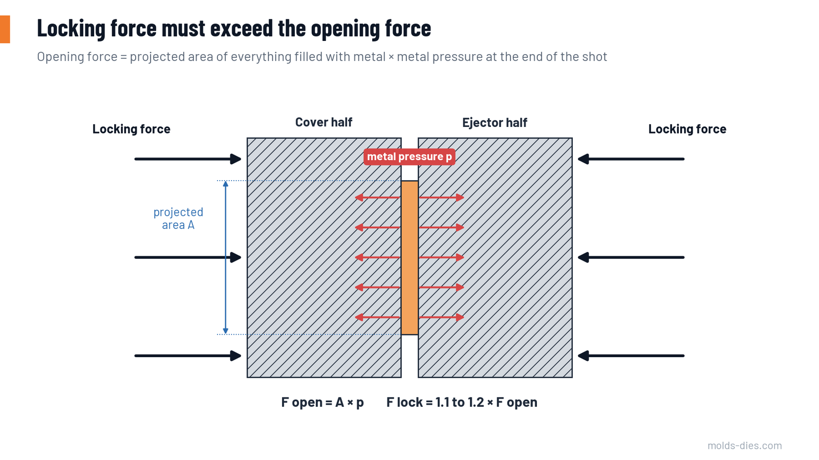
- Opening force (kN) = projected area (cm²) × metal pressure (bar) ÷ 100
- Required locking force = opening force × 1.1 to 1.2
The safety factor covers pressure peaks at the end of fill, when the moving plunger and hydraulic oil are stopped suddenly.
Three corrections are often forgotten:
- Slides. Metal pressure on a slide core pushes the slide back against its wedge lock, and the wedge converts part of that force into an opening force on the die. Add the slide face area × pressure × the tangent of the wedge angle to the opening force.
- Off-centre cavities. If the centre of the projected area is not on the machine centre line, the tie bars are loaded unequally. The bar nearest the cavity may reach its limit while the total force still looks adequate. Keep the centre of pressure within the limits the machine builder gives, or move the cavity.
- Die size. A die much smaller than the platens bends them. As a rule, the die should cover at least about half to two-thirds of the tie-bar spacing in each direction.
Step 4: Shot volume and sleeve fill ratio
The shot is everything poured into the sleeve: casting, overflows, runner and biscuit.
- Shot volume (cm³) = shot mass (g) ÷ liquid density (2.5 g/cm³ for aluminum)
- Sleeve volume = plunger area × active sleeve length (from the plunger face in the back position to the die parting face)
- Fill ratio = shot volume ÷ sleeve volume
Aim for a fill ratio of 40–60 %. Below about 30 %, the metal lies as a shallow pool, cools against the sleeve, and the wave formed by the slow shot folds a lot of air into it. Above about 70 %, metal may spill from the pour hole and the slow phase becomes difficult to control.
Step 5: Plunger diameter
The plunger diameter links four results, so it is chosen last:
- Metal pressure (bar) = intensified shot force (kN) × 100 ÷ plunger area (cm²)
- Fast-shot speed needed = flow rate at the gate ÷ plunger area
- Fill ratio, as above
- Biscuit diameter and its projected area
A smaller plunger gives higher metal pressure and a better fill ratio, but needs a higher plunger speed for the same flow. A larger plunger gives more flow at less pressure.
Worked example
An aluminum housing has a projected area of 350 cm² and must be mechanically sound (600 bar). The casting with overflows weighs 1.2 kg, the runner 0.35 kg and the biscuit 0.45 kg. The gate calculation asks for a flow rate of 9.6 litres per second.
Locking force
| Quantity | Calculation | Result |
|---|---|---|
| Total projected area | 350 × 1.3 | 455 cm² |
| Opening force | 455 × 600 ÷ 100 | 2,730 kN |
| Required locking force | 2,730 × 1.2 | 3,276 kN |
| Machine class | next standard size with margin | 4,000 kN (about 400 tonnes) |
Shot end, for a machine with 350 kN intensified shot force and 400 mm active sleeve length:
| Plunger diameter | Plunger area (cm²) | Metal pressure (bar) | Fill ratio | Fast-shot speed for 9.6 L/s (m/s) |
|---|---|---|---|---|
| 60 mm | 28.3 | 1,237 | 71 % | 3.4 |
| 70 mm | 38.5 | 909 | 52 % | 2.5 |
| 80 mm | 50.3 | 696 | 40 % | 1.9 |
The shot volume is 2,000 g ÷ 2.5 = 800 cm³. The 70 mm plunger is the best choice: it delivers more than the 600 bar required, the sleeve is half full, and the speed is moderate. The 60 mm plunger overfills the sleeve. The 80 mm plunger works but leaves little pressure reserve.
Step 6: Check the dynamic capacity
Static pressure is not the whole story. During the fast shot, the machine must push the required flow through the gate, and the pressure available falls as the flow rises. Machine builders show this as a line on a pressure–flow diagram; the gate has its own line, because the pressure needed to push metal through a fixed gate area rises with the square of the flow.
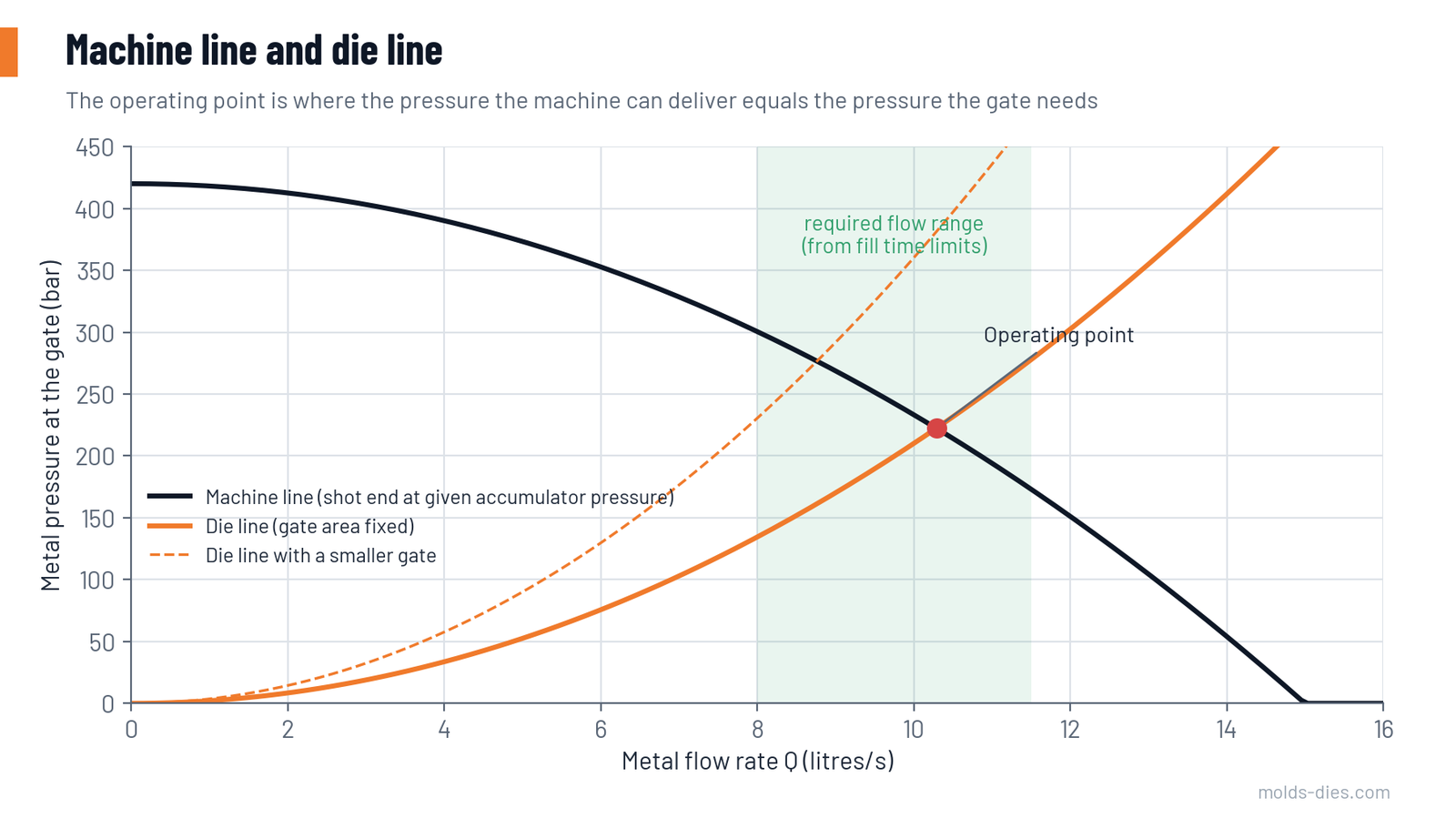
The operating point is where the two lines cross. It must lie inside the flow range that the fill time requires. If it falls to the left of that range, the machine cannot fill the cavity in time: open the gate, use a larger plunger, raise the accumulator pressure, or choose a machine with a stronger shot end.
Step 7: Check the die space
| Item | What to compare |
|---|---|
| Tie-bar spacing | Die width and height, including slides and their cylinders when open |
| Die height range | Minimum and maximum die thickness of the machine |
| Opening stroke | Casting depth + core length + room for the extractor or robot |
| Ejector stroke and force | Deepest feature to be ejected, number of pins |
| Shot position | Sleeve position (centre or lowered) against the runner layout |
| Core pull circuits | Number of hydraulic slides on the die |
Common mistakes
| Mistake | Consequence |
|---|---|
| Using only the casting's projected area | Locking force 25–40 % too low; flash from the first shift |
| Using machine tonnage as the only criterion | Shot end too weak or sleeve badly filled |
| Raising intensification pressure later without re-checking | Die blows open; flash wears the parting face |
| Largest available plunger "for safety" | Fill ratio below 30 %, air porosity |
| Ignoring slides and off-centre load | Uneven flash on one side, tie-bar damage over time |
Key takeaways
- Locking force = total projected area × metal pressure × 1.1–1.2, including runners, overflows, biscuit and slide effects.
- Choose the plunger so that pressure, fill ratio (40–60 %) and plunger speed are all acceptable together.
- Confirm on the pressure–flow diagram that the machine can deliver the flow the gate needs.
- Check die space, strokes and core circuits before committing a die to a machine.
Related Articles
Die Life in HPDC: Heat Checking, Soldering and How to Delay Them
The main failure modes of die casting dies — heat checking, soldering, erosion and gross cracking — and the design, steel and process measures that extend die life.
Overflows, Vents and Vacuum: Getting the Air Out of the Die
Practical rules for placing and sizing overflows, vents, chill vents and vacuum channels in high-pressure die casting dies.
Porosity in Die Casting: Gas vs. Shrinkage, Causes and Fixes
How to tell gas porosity from shrinkage porosity in die castings, what causes each one, and the process and die changes that actually reduce them.
HPDC Gating Design: Gate Area, Gate Velocity and Fill Time
A step-by-step method to size the gate of a high-pressure die casting die from cavity fill time and gate velocity, with a worked example and reference tables.
High-Pressure Die-Casting Process
Explore the high-pressure die-casting process, a method for producing metal parts with high precision and uniformity. Learn its benefits and applications