Additive Manufacturing for Toolmakers: Processes, Materials and Where Each Fits
-
 Mohamed Aboelfotouh
- Sector : Additive Manufacturing
- Oct. 9, 2026, 6:10 a.m.
Additive manufacturing builds a part by adding material layer by layer instead of cutting it from a block. For a tool shop it is not a replacement for milling, EDM and grinding. It is a fourth capability that does three things the other machines cannot: it makes internal geometry such as curved cooling channels, it makes a usable shape with no tooling and almost no programming, and it adds material to an existing tool. This article describes the processes that matter for molds and dies, what each one delivers, and which jobs it suits.
What additive changes for a toolmaker
Every tooling application of additive manufacturing falls into one of four groups. Knowing which group a job belongs to decides the process.
| Group | What is printed | Typical example | Main process |
|---|---|---|---|
| Better tooling | A steel insert with features that cannot be machined | Core insert with conformal cooling | Laser powder bed fusion |
| Faster tooling | A short-life tool made in days | Polymer mold insert for 50 molded parts | Stereolithography, material jetting |
| No tooling | The part itself | 200 nylon housings, 10 metal brackets | Powder bed (polymer or metal) |
| Repaired tooling | New material on an old tool | Rebuilt edge on a die casting insert | Directed energy deposition |
In all four groups the printed surface is a near-net shape. Fits, shut-offs, sealing faces and polished cavity surfaces are still machined. The printer joins the machine shop; it does not bypass it.
The metal processes
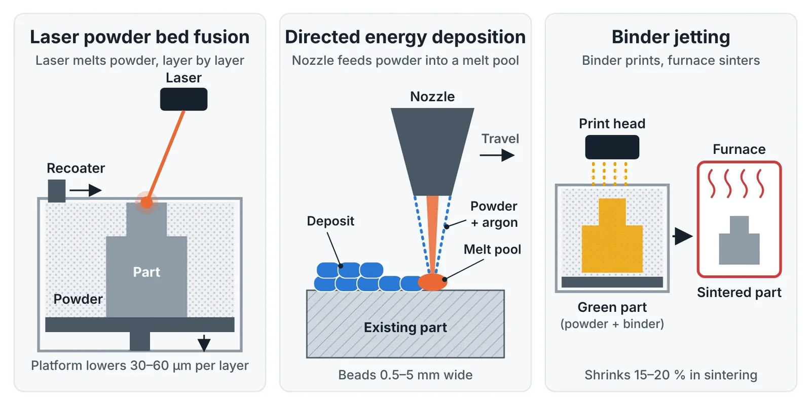
Three metal processes are relevant to tooling. They differ in how the metal is delivered and how it is fused.
Laser powder bed fusion (LPBF)
A recoater spreads a powder layer 30–60 µm thick and a laser melts the cross-section of the part. The platform drops by one layer and the cycle repeats. Density is above 99.5 % and the mechanical properties after heat treatment match wrought steel closely. Any internal shape is possible as long as the loose powder can be removed afterwards. This is the process for conformal-cooled inserts, vented inserts and small complex cores.
The limits are size, speed and surface. Common machines build about 250 × 250 × 300 mm. Build rates for steel are in the range of 5–20 cm³ per hour for each laser, so a fist-sized insert takes one to two days. The as-built surface is rough and every functional face needs stock for machining.
Directed energy deposition (DED)
A nozzle feeds powder or wire into a melt pool created by a laser or an electric arc. The head moves on a CNC machine or a robot and deposits beads 0.5–5 mm wide. DED works on existing parts and on curved surfaces, so it is the process for repair, hardfacing and adding features to a finished insert. Laser cladding is the same process used for surface layers. Accuracy is low and the deposit is always machined afterwards.
Binder jetting
A print head deposits liquid binder on a powder bed. The result is a fragile "green" part that is sintered in a furnace, where it shrinks by 15–20 % in each direction. There is no melting during printing, so there is little residual stress and no support structure. The process is fast and suits small parts in quantity. The sintering shrinkage limits accuracy on larger parts. In tooling its most useful form is sand binder jetting, which prints sand molds and cores for casting without a pattern.
| Property | LPBF | DED (laser, powder) | Binder jetting (metal) |
|---|---|---|---|
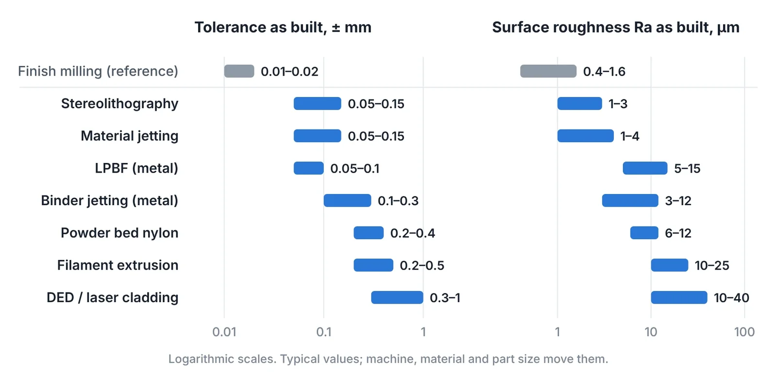
| Feature accuracy as built | ±0.05 to ±0.1 mm | ±0.3 to ±1 mm | ±0.1 to ±0.3 mm on small parts |
| Surface roughness Ra as built | 5–15 µm | 10–40 µm | 3–12 µm |
| Density | > 99.5 % | > 99.5 % | 96–99 % |
| Tooling materials | Maraging 1.2709, H13, stainless mold steels, copper alloys | Tool steels, cobalt and nickel alloys, carbide-filled alloys | 17-4PH, 316L, some tool steels |
| Internal channels | Yes | Limited | Yes, in small parts |
| Works on an existing part | Only on a flat preform | Yes | No |
| Main tooling use | Conformal-cooled inserts | Repair, cladding, design changes | Small inserts, sand molds and cores |
The polymer processes
Polymer printers cost far less than metal ones and most tool shops start here. Four processes cover almost every need.
| Process | How it works | Accuracy | Surface | Use in the tool shop |
|---|---|---|---|---|
| Stereolithography (SLA, DLP) | Light cures liquid resin layer by layer | ±0.1 mm | Smooth, Ra 1–3 µm | Short-run mold inserts, masters for silicone molds, casting patterns |
| Material jetting | Print heads jet resin droplets cured by UV light | ±0.1 mm | Smooth | Short-run mold inserts, appearance models |
| Powder bed (SLS, MJF) | Laser or infrared energy fuses nylon powder | ±0.3 mm | Grainy, Ra 6–12 µm | End-use parts in small batches, grippers, fixtures |
| Filament extrusion (FFF) | A nozzle lays down molten filament | ±0.2 to ±0.5 mm | Visible layers | Jigs, fixtures, check gauges, forming dies for thin sheet |
Two properties decide whether a polymer print can act as a tool: stiffness at temperature and surface quality. Filled high-temperature resins from SLA keep their shape against molten plastic for tens to hundreds of shots. Nylon powder bed parts are tough but too rough and too porous for a cavity surface. Filament parts are strong in the layer plane and weak across it, so they are loaded in compression, as in a forming die or a fixture.
Where each process fits
| Job | Process | Why | Watch for |
|---|---|---|---|
| Core or cavity insert with a hot spot that drilled lines cannot reach | LPBF in maraging steel | Channels follow the cavity surface | Powder removal, water quality, machining stock |
| Worn or chipped edge, cracked insert, late design change | DED or laser cladding | Low heat input, CNC-controlled deposit | Remove nitrided layer and cracks first |
| 20–100 molded parts in the real plastic | SLA or material jetting insert in a steel frame | Insert ready in one or two days | Low pressure, long cycle, large draft |
| 50–500 plastic parts, no tooling budget | Powder bed nylon, printed directly | No tool, no draft, design can change between batches | Material is nylon, not the production resin |
| Fixtures, soft jaws, check gauges, robot grippers | FFF or powder bed | Cheap, light, made overnight | Add steel bushings at wear points |
| Forming die for 10–300 sheet metal parts | FFF with fibre-filled nylon or polycarbonate | Loaded in compression, easy springback iterations | No cutting edges in polymer |
| 5–50 castings before a die exists | Sand binder jetting | Sand mold with no pattern | Properties differ from die cast parts |
| Gas vents in a closed area of the cavity | LPBF insert with a porous zone | Air escapes through the steel itself | Pores clog; plan cleaning |
Additive is the wrong choice where conventional machining is already fast. A flat insert with straight drilled lines, a simple electrode or a block-shaped core is cheaper and more accurate from bar stock. The rule is to print the geometry that cannot be cut and to cut everything else.
What printing does not give you
- Finished surfaces. Plan 0.3–0.5 mm of stock on every fit, shut-off and cavity face, and more on large parts.
- Optical polish without risk. Residual pores of 10–50 µm can open during polishing. Printed steel reaches a good technical polish but is a risk for mirror surfaces.
- Size. Most LPBF machines stop near 300 mm. Larger tools are built as hybrid inserts or left to conventional methods.
- Low material cost. Powder costs several times more than bar stock and machine time is charged by the hour. A printed insert is paid back by cycle time, scrap or lead time, not by its own price.
- Freedom from design rules. Overhangs below about 45° need supports, loose powder must have a way out, and residual stress distorts thin sections.
Buy a machine or buy the service
The two families call for different decisions.
- Polymer first, in-house. A resin or filament printer pays back on fixtures, gauges and trial inserts within months and builds design experience at low risk.
- Metal through a service bureau. A metal LPBF installation needs the machine, powder handling, inert gas, a furnace and trained staff. Until there is steady work for it, buy the builds and keep design and finishing in-house.
- Keep the value in the tool shop. The bureau prints. The toolmaker designs the channels, defines the stock, heat treats, machines, polishes and guarantees the tool. That is where the know-how and the margin are.
- Review when volume is stable. When builds are ordered every week and lead time from the bureau limits delivery, the case for an in-house machine can be calculated from real numbers.
A build request to a bureau should state the material and required hardness, the heat treatment, the build orientation if it matters, the faces that carry machining stock, the channel openings that must be free of powder, and the acceptance test, usually a flow and pressure test of each circuit.
Common mistakes
| Mistake | Result | Correct approach |
|---|---|---|
| Printing a shape that could be milled | Higher cost, lower accuracy | Print only what machining cannot produce |
| No machining stock on functional faces | Insert cannot be fitted | Add 0.3–0.5 mm and define datums before the build |
| Closed or dead-end channels | Trapped powder, blocked cooling | Every channel has an inlet, an outlet and a clear path |
| Judging a printed polymer insert by steel mold standards | Disappointment with life and tolerance | Use it for tens of parts, not thousands |
| Validating production properties on printed parts | Wrong conclusions about strength and shrinkage | Test function and fit; confirm properties on tooled parts |
| Buying a metal printer before the workload exists | Idle capital | Start with a bureau and build demand |
Key takeaways
- Additive manufacturing gives a tool shop internal geometry, tool-free shapes and local material addition. It does not remove the need for machining.
- LPBF makes dense steel inserts with conformal cooling, DED repairs and modifies existing tools, and binder jetting serves small parts and sand molds.
- Polymer printers are the low-cost entry: resin for short-run mold inserts, nylon for direct parts, filament for fixtures and forming dies.
- Print what cannot be cut, leave stock on everything that must fit, and start metal work through a bureau while keeping design and finishing in-house.
Related Articles
3D Printed Mold Inserts for Short-Run Injection Molding
How to design and run 3D printed polymer mold inserts for 10 to 100 molded parts: materials, draft, gates, process settings, insert life and failure modes.
Small Batches: Print the Part, Print the Tool, or Cut the Tool?
Break-even calculation for small batches: 3D printed parts, printed mold inserts, aluminum molds and steel molds, with routes for metal and sheet metal parts.
Repairing Molds and Dies with Laser Cladding and Directed Energy Deposition
Mold and die repair by TIG, laser welding and laser cladding compared: heat-affected zone, dilution, filler choice, repair procedure and when to replace.
Printing Tool Steel: Maraging, H13 and What Happens After the Build
Printable tool steels compared, with the full post-processing route: stress relief, age hardening, machining allowance, polishing limits and surface treatment.
Conformal Cooling in Injection Molds and Die Casting Inserts: Design Rules and Payback
Design rules for conformal cooling channels in printed mold inserts: diameter, pitch, distance to cavity, flow, hybrid inserts, HPDC limits and payback.