
Preventive Maintenance Program for Molds and Dies
-
 Mohamed Aboelfotouh
- Sector : General
- Oct. 2, 2026, 6:42 p.m.
A mold or die that fails in the press stops production, damages itself further while it fails, and has to be repaired under time pressure. Most of those failures give warning: a vent filling up, a spring losing force, a punch edge rounding, a water channel scaling. Preventive maintenance is the routine that finds these while they are small. This article describes a program that a toolroom of any size can run: three service levels, intervals based on counted cycles, checklists, spare parts and records.
The three service levels
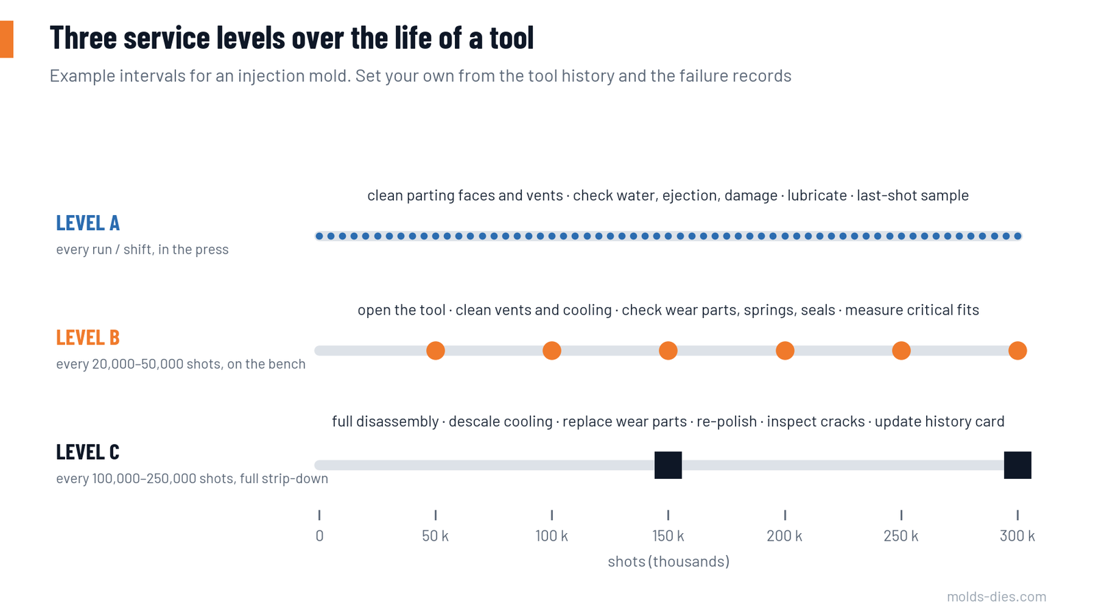
| Level | Where and when | Who | Purpose |
|---|---|---|---|
| A: in-press care | At every start, during the run, and at the end of every run | Setter or operator | Keep the tool clean, lubricated and undamaged; notice changes |
| B: bench service | At a set number of cycles, or after each run for short-run tools | Toolroom | Open the tool, clean it properly, check wear parts, correct small faults |
| C: major service | At a larger set number of cycles | Toolroom, with planning | Full strip-down, replacement of wear parts, measurement, refurbishment |
Level A: every run
| When | Task |
|---|---|
| Before mounting | Check the tool is the right one and at the right revision; inspect connectors, hoses, lifting points |
| At start-up | Bring the tool to temperature before production; check water flow in every circuit; check ejection and slides by hand cycle |
| During the run | Clean parting faces and vents at a fixed frequency; lubricate guide pins and slides as specified; watch for flash, burrs, drag marks, noise |
| At the end of the run | Keep the last-shot sample (last part, or last strip from a progressive die) with the tool; blow out water; clean; apply rust preventive; close the tool |
| Always | Write any fault or unusual observation on the tool tag before the tool leaves the press |
The last-shot sample is the simplest diagnostic aid there is. It shows the toolroom the condition of every cavity, gate, edge and punch at the end of the run.
Level B: bench service
| Area | Checks |
|---|---|
| Cleaning | Remove residue from cavities, vents, ejector holes; do not use abrasives on polished or textured surfaces |
| Parting and shut-off faces | Look for hobbing, flash marks, damage; blue the faces if flash was reported |
| Vents | Measure depth; restore if closed or peened over |
| Ejection | Pins move freely; no galling; return pins and springs intact |
| Slides, lifters, cams | Wear plates, gibs and locks; springs and detents; lubrication |
| Cutting elements (stamping) | Edge condition; burr height on the last strip; sharpen by the defined amount; reset punch heights with shims |
| Cooling | Flow test per circuit; leak test; check seals and fittings |
| Hot runner | Heater resistance and insulation; thermocouples; nozzle tips |
| Fasteners and guides | Torque of main screws; guide pins and bushes for scoring |
| Result | Record findings; replace what is at its limit; release or hold the tool |
Level C: major service
- Disassemble completely and clean every component.
- Descale cooling channels and flush them.
- Replace all wear parts on the list: seals, springs, worn pins, bushes, wear plates, punches and die buttons near their limit.
- Measure critical dimensions of cavities, inserts and cutting clearances; compare with the original report.
- Inspect for cracks at known risk points; use dye penetrant where needed.
- Re-polish or re-texture worn surfaces; renew coatings or nitriding where specified.
- For die-casting dies, carry out the stress-relief temper due at this interval.
- Reassemble, test functions on the bench, and run a short trial if any forming surface was changed.
- Update the tool history card and reset the interval counters.
Intervals
Count cycles, not calendar time. A tool that runs one week a year and a tool that runs every day do not need service on the same dates. Fit a counter to every tool, or take the count from the press records.
| Tool type | Level B interval | Level C interval | Notes |
|---|---|---|---|
| Injection mold, unfilled resin | 20,000–50,000 shots | 100,000–250,000 shots | Shorter for glass-filled or corrosive resins and for molds with many moving parts |
| Die-casting die | After each run, or 5,000–10,000 shots | 20,000–50,000 shots | Combine with stress tempering; inspect heat checks at each service |
| Stamping or progressive die | By sharpening interval: commonly 50,000–300,000 hits, depending on material and tool steel | 1–2 million hits | Set the sharpening interval from burr height on the last strip |
| Extrusion die | After every run: clean, inspect, polish bearings | By number of runs or tonnes extruded: re-nitride | Record billets or kilograms per run |
These are starting values. After a few cycles of the program, adjust each tool's interval from its own history: if a level B service finds nothing, extend the interval; if the tool fails before the service is due, shorten it.
The tool history card
One card or database record per tool, kept for its whole life.
| Section | Contents |
|---|---|
| Identity | Tool number, part number and revision, cavities, customer, owner of the tool |
| Technical data | Size, weight, press or machine, steel grades and hardness, surface treatments, hot runner type |
| Counters | Total cycles; cycles since last B and C service |
| Service log | Date, cycle count, level, findings, work done, parts replaced, hours, name |
| Fault log | Date, cycle count, fault, cause, corrective action, downtime |
| Changes | Engineering changes with date and revision |
| Spare parts | List with quantities in stock |
Review the cards regularly. A fault that appears twice on the same tool is a design or process issue to solve at the root, not a maintenance task to repeat.
Spare parts
| Category | Examples | Policy |
|---|---|---|
| Consumables | Seals, O-rings, springs, standard ejector pins | Stock for all tools by standard size |
| Tool-specific wear parts | Gate inserts, core pins, punches, die buttons, nozzle tips | At least one set per tool; reorder when used |
| Long-lead critical parts | Special cores, slides, hot runner components | Hold one spare for tools whose stoppage would stop a customer |
Standardizing component sizes across tools at the design stage reduces the spare parts stock more than any other measure.
Storage
- Clean, dry and treated with rust preventive; water blown out of all channels.
- Closed, with a safety strap or bar between the halves; never stored open.
- On racks rated for the weight, each position labelled.
- Tagged with status: ready for production, service required, or under repair.
- Stored with its last-shot sample, its own hoses or connectors if special, and its process sheet.
Measuring whether the program works
| Indicator | Target direction |
|---|---|
| Unplanned tool-related downtime (hours per month) | Down |
| Share of toolroom hours spent on planned work compared with breakdowns | Planned share up |
| Repair cost per 1,000 parts, by tool | Down, and stable |
| Scrap attributed to tool condition | Down |
| Services carried out on time | Above 90 % |
Getting started in five steps
- List all active tools and rank them by importance: volume, customer risk, known problems.
- Fit or assign a cycle count to the top group.
- Write one-page checklists for levels A and B for each tool type.
- Open a history card for each tool, starting with what is known today.
- Run the program on the top group for three months, review the findings, then extend it to the rest.
Common mistakes
| Mistake | Result |
|---|---|
| Intervals by calendar instead of cycles | Busy tools under-serviced, idle tools over-serviced |
| No last-shot sample | Toolroom has to guess the tool's condition |
| Faults reported verbally | Information lost between shifts |
| Tool stored wet or open | Rust in channels and on cavities; damaged edges |
| Running a tool "just to finish the order" with a known fault | Small repair becomes a major one |
| Records kept but never reviewed | Repeated faults stay unsolved |
Key takeaways
- Use three levels: care at the press every run, bench service at a counted interval, and a full strip-down at a longer counted interval.
- Base intervals on cycles and adjust them from each tool's own history.
- Keep a history card and a last-shot sample for every tool.
- Hold spare wear parts per tool, store tools dry and closed, and measure unplanned downtime to prove the program pays.
Related Articles
How to Estimate the Cost of a Mold or Die
A structured method for estimating tooling cost: material, standard parts, design and machining hours, heat treatment, trials, overhead and margin.
Surface Treatments for Tooling: Nitriding, PVD and When Each Fits
A comparison of nitriding, PVD, CVD, TD and hard chrome for molds and dies: hardness, layer depth, process temperature and where each one works.
Laser Hardening in Manufacturing
Laser hardening is a precise surface heat treatment that improves wear resistance and durability of steel components with minimal distortion compared to traditional hardening methods.
Heat Treatment: Concept and Methods
Understand the various heat treatment methods like annealing, quenching, and tempering, used to alter the properties of steel and other materials
Understanding Molds and Dies: Differences, Types, and Applications
Explore the differences between molds and dies, their types, and applications in modern manufacturing. Learn how these tools shape raw materials into finished products
Die Life in HPDC: Heat Checking, Soldering and How to Delay Them
The main failure modes of die casting dies — heat checking, soldering, erosion and gross cracking — and the design, steel and process measures that extend die life.