Hot Runner vs. Cold Runner: When Each One Pays Off
-
 Mohamed Aboelfotouh
- Sector : Plastic Injection
- Oct. 2, 2026, 4:07 p.m.
A hot runner keeps the plastic molten all the way to the gate, so no runner is molded and thrown away with each shot. A cold runner is molded and ejected with the parts. The hot runner costs more to buy and to maintain; the cold runner costs more per part in material and cycle time. The choice is an economic calculation with a few technical conditions attached. This article sets out both.
How the two systems differ
| Cold runner | Hot runner | |
|---|---|---|
| Runner | Solidifies and is ejected every cycle | Stays molten in a heated manifold and nozzles |
| Mold cost | Lower | Higher: manifold, nozzles, controller, wiring, extra plates |
| Material loss | Runner must be reground or scrapped | None from the runner |
| Cycle time | Often set by the thick sprue and runner | Set by the part only; usually shorter |
| Opening stroke | Longer, to let the runner fall | Shorter |
| Colour and material change | Fast | Slower; material in the manifold must be purged |
| Start-up | Simple | Needs heating time and a start-up procedure |
| Maintenance | Almost none | Heaters, thermocouples, seals, nozzle tips, valve pins |
| Gate quality | Depends on gate type | Good with thermal gates, best with valve gates |
| Process control | Runner pressure loss changes with temperature | Lower pressure loss, more freedom in gate position |
Technical conditions that decide before cost
Check these first. Any of them can settle the question on its own.
| Condition | Points toward |
|---|---|
| Regrind not allowed (medical, optical, some food-contact and engineering parts) | Hot runner |
| Runner weight is large compared with part weight (small parts, many cavities) | Hot runner |
| Very large part needing several gates or sequential filling | Hot runner with valve gates |
| Heat-sensitive material (rigid PVC, some flame-retardant grades, some POM grades) | Cold runner, or a hot runner specifically designed for that material |
| Frequent colour changes on short runs | Cold runner |
| Low total volume or prototype tool | Cold runner |
| Limited maintenance skills or spare parts on site | Cold runner |
| Gate vestige must be almost invisible | Valve-gate hot runner |
| Automatic production without runner handling | Hot runner, or cold runner with tunnel gates and a sprue picker |
The cost comparison
Compare the two molds over the quantity you expect to produce. Only the costs that differ need to be included.
Extra investment for the hot runner
- hot runner system (manifold, nozzles) and temperature controller;
- extra design, machining and assembly;
- spare parts kit.
Savings per part with the hot runner
- Runner material. Runner weight per shot ÷ number of cavities × material price × the share that cannot be reused. If all regrind goes back into the same part, the loss is only the cost of grinding and the quality risk. If no regrind is allowed, the whole runner is lost.
- Cycle time. Seconds saved × machine hourly rate ÷ 3,600 ÷ number of cavities. Cycle reductions of 10–25 % are common when the cold runner or sprue is the thickest section in the shot.
- Handling. Runner separation, grinding and labour, if not automated.
Extra cost per part with the hot runner
- energy for the heaters;
- maintenance and spare parts;
- purging material at colour changes.
Break-even quantity = extra investment ÷ net saving per part
Worked example
A four-cavity mold makes a 20 g ABS part. The machine costs 30 per hour (any currency).
| Item | Cold runner | Hot runner |
|---|---|---|
| Mold price | 30,000 | 42,000 |
| Cycle time | 24 s | 20 s |
| Machine cost per part | 24 × 30 ÷ 3,600 ÷ 4 = 0.050 | 20 × 30 ÷ 3,600 ÷ 4 = 0.042 |
| Runner per shot | 16 g (4 g per part) | none |
| Runner material lost (no regrind allowed, 2.5 per kg) | 0.010 | 0 |
| Energy and maintenance per part | — | 0.002 |
| Differing cost per part | 0.060 | 0.044 |
Net saving with the hot runner: 0.016 per part. Extra investment: 12,000.
Break-even = 12,000 ÷ 0.016 = 750,000 parts.
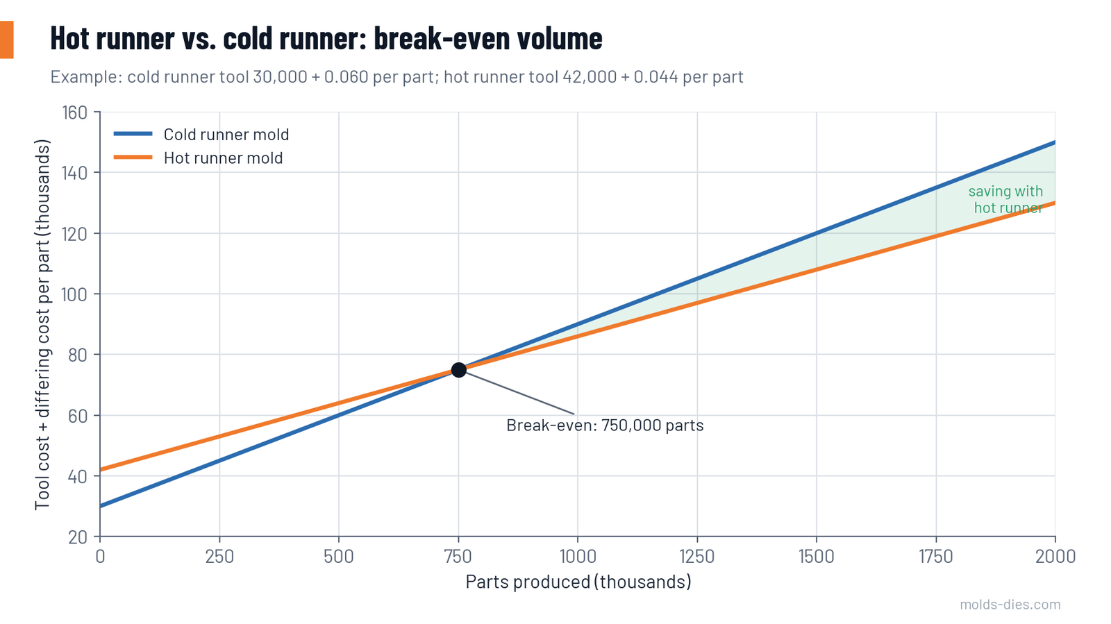
If the planned volume is 300,000 parts, the cold runner is cheaper. At 2 million parts, the hot runner saves about 20,000 over the life of the tool. The example also shows how sensitive the result is:
| Change in assumption | New break-even |
|---|---|
| Regrind fully reusable (runner loss falls to about 0.002) | about 1,500,000 parts |
| Eight cavities instead of four, same runner per part, extra investment 20,000 | about 1,650,000 parts |
| Cycle saving of 6 s instead of 4 s | about 590,000 parts |
| Material at 5.0 per kg instead of 2.5, no regrind | about 460,000 parts |
Run the calculation with your own figures before deciding. The two inputs that matter most are whether regrind can be used and how much cycle time the runner really costs.
Intermediate solutions
The choice is not always all or nothing.
| Solution | What it is | When to use |
|---|---|---|
| Hot sprue bushing | One heated nozzle replacing the cold sprue, feeding a short cold runner | Low-cost first step; removes the thickest part of the runner |
| Hot runner to cold sub-runners | Manifold with a few nozzles, each feeding a small cold runner with tunnel gates | Many small cavities; fewer nozzles to buy and maintain |
| Insulated runner | Thick unheated runner that stays molten in its core | Rare today; only for fast-cycling, easy materials |
| Three-plate cold runner | Pin-point gating without heaters | When central gating is needed at low volume |
Thermal gate or valve gate
| Thermal (open) gate | Valve gate | |
|---|---|---|
| Shut-off | Plastic freezes in the gate | A pin closes the gate mechanically |
| Vestige | Small raised point | Flat ring mark, almost invisible |
| Gate size | Small, to freeze reliably | Can be large: less shear, lower pressure |
| Stringing and drooling | Possible | Eliminated |
| Sequential filling | No | Yes |
| Cost and maintenance | Lower | Higher: actuators, pins, seals |
What to specify when ordering a hot runner mold
- Material grade and whether colours will change.
- Balanced manifold with the same flow length to every nozzle.
- One control zone and one thermocouple per nozzle and per manifold section.
- Nozzle tips and heaters replaceable from the parting line where possible.
- Wiring diagram and connector layout to your plant standard.
- Thermal insulation between the hot half and the machine platen.
- A spare parts kit: at least one nozzle heater, thermocouple and tip of each type.
- A documented start-up and shut-down procedure.
Common mistakes
| Mistake | Consequence |
|---|---|
| Choosing a hot runner without a maintenance plan or spares | A failed heater stops a whole mold for days |
| Ignoring colour changes in the calculation | Purging scrap wipes out the runner saving |
| Counting full runner weight as saving when regrind is reused | Break-even looks twice as good as it is |
| Unbalanced manifold corrected by nozzle temperatures | Cavities differ in weight and dimension |
| Starting the mold without a soak time | Cold slugs, damaged gates, leaks at the manifold |
Key takeaways
- Check the technical conditions first: regrind policy, material sensitivity, colour changes, gate appearance.
- Then calculate break-even = extra investment ÷ net saving per part, using your own cycle and material figures.
- Regrind policy and cycle-time saving dominate the result.
- Hot sprue bushings and hot-to-cold layouts offer much of the benefit at lower cost and risk.
Related Articles
Exploring the Plastic Injection Molding Process & Types
Learn about the plastic injection molding process, its types, and how it produces high-quality plastic parts for industries like automotive and electronics
Mold Steel Selection by Production Volume and Resin
How to choose injection mold steel — P20, H13, stainless and high-hardness grades — from production volume, resin abrasiveness, corrosion and surface finish.
Injection Molding Defects: A Troubleshooting Guide
Short shots, flash, sink marks, warpage, weld lines, burn marks, splay and jetting: causes and a structured order of corrective actions.
Gate Types and Gate Location: How to Choose
A practical guide to choosing the gate type and gate position in injection molds: edge, fan, tunnel, pin-point, diaphragm and valve gates compared.
Injection Mold Cooling Design: Channel Layout and Cycle Time
Sizing and placing cooling channels in injection molds: diameter, pitch and depth rules, turbulent flow, circuit layout and their effect on cycle time.