
Extrusion Defects: Die Lines, Pick-Up, Tearing and Their Fixes
-
 Mohamed Aboelfotouh
- Sector : Aluminum Extrusion
- Oct. 2, 2026, 4:08 p.m.
Most defects on aluminum extrusions come from one of three places: the die, the billet, or the press settings. A fourth group arises after the die, during quenching, pulling, stretching and ageing. Knowing which area to look at first saves trials and scrap. This article covers nine common defects, how to recognize them, and what to change.
Where to look first
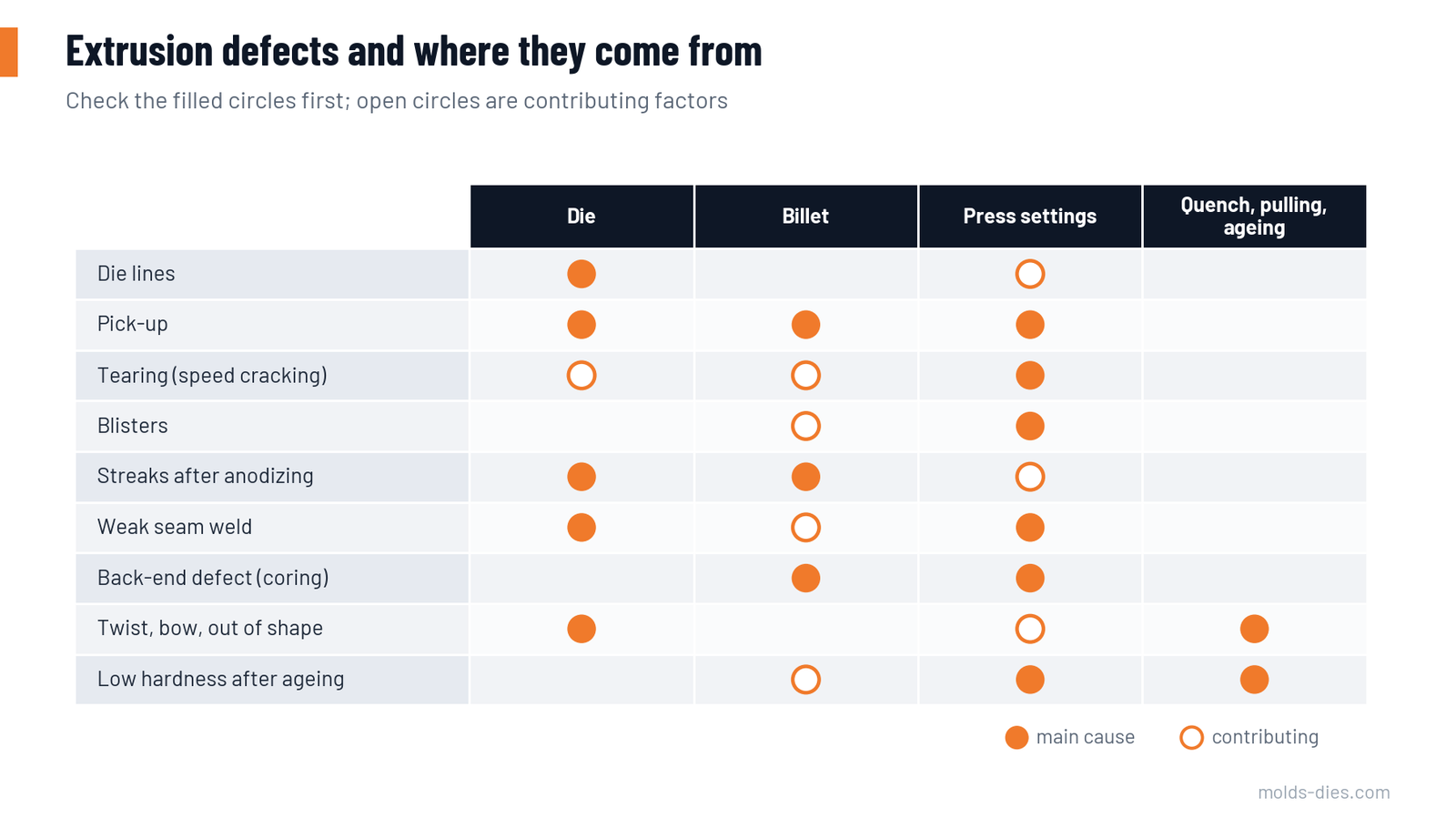
Before changing anything, answer three questions:
- Is the defect at the same position on the profile every time? A fixed position points to the die. A random position points to the billet or to handling.
- Does it change along the length of one extrusion? Defects that get worse toward the end of each billet point to temperature rise or to the back end of the billet. Defects only at the start of each billet point to the billet-to-billet weld or to air.
- Does it appear on other dies running the same billet lot? If yes, check the billet and the press before the die.
The nine defects
1. Die lines
Continuous fine lines along the extrusion direction, always in the same place.
| Cause | Action |
|---|---|
| Worn, scored or rough bearing | Re-polish the bearing; re-nitride if the hard layer is worn through |
| Aluminum build-up on the bearing | Clean the die; check that the bearing is flat and square to the die face |
| Hard particles embedded in the bearing | Check billet cleanliness and the filtration at the cast house |
| Bearing too long for the wall | Shorten or relieve the bearing |
A certain level of die lines is normal. Agree on a limit sample with the customer, especially for anodized finishes.
2. Pick-up
Short torn marks, often shaped like a comet with a small lump at the head, scattered along the surface.
| Cause | Action |
|---|---|
| Exit temperature too high | Lower the ram speed or the billet temperature; use nitrogen cooling at the die |
| Poorly homogenized billet | Check the homogenizing practice and the cooling rate after it with the billet supplier |
| Bearing condition | Polish and nitride; avoid long bearings on thin walls |
| Dirty die or aluminum film left after caustic cleaning | Improve cleaning and inspection before the die goes to the press |
3. Tearing (speed cracking)
Fine transverse cracks, usually on edges, thin tips and corners. In severe cases the edge looks like a saw.
The surface has reached the temperature at which the lowest-melting constituents of the alloy begin to melt, and the friction in the bearing pulls it apart.
| Cause | Action |
|---|---|
| Ram speed too high for the billet temperature | Reduce speed, or reduce billet temperature and keep the speed |
| Temperature rising along the stroke | Use taper-heated billets or a decreasing speed profile |
| Unbalanced die: tip or thin wall running slow and being stretched | Correct the bearing so the area is fed |
| Alloy at the top of its composition range, or poor homogenization | Review the billet certificate |
4. Blisters
Raised bubbles on the surface, often appearing near the front of each extrusion or after heat treatment.
| Cause | Action |
|---|---|
| Air trapped between billet and container | Use a decompression ("burp") cycle after upsetting; upset slowly |
| Billet much smaller than the container bore, or a worn, barrel-shaped liner | Check billet diameter and liner wear |
| Billet ends not square, or oxide and lubricant folded in | Check the saw cut; keep lubricant on the dummy block and shear to a minimum |
| Uniformly heated billet upsetting from the back | Taper heat with the front end hotter so the billet upsets from the die end and pushes air backward |
5. Streaks after anodizing
Bands of different gloss or colour that become visible only after etching and anodizing.
| Type | Cause | Action |
|---|---|---|
| Bearing streaks | Sudden change in bearing length, or a bearing transition opposite a rib or screw boss | Blend bearing lengths gradually; adjust the design at junctions |
| Weld streaks | Seam welds in hollow profiles on a visible face | Move the bridge position; increase welding chamber height |
| Structural streaks | Coarse or uneven grain, surface segregation of the billet flowing into the profile | Check billet quality and scalping; increase the butt length |
| Temperature streaks | Uneven cooling on the run-out table | Check quench uniformity and contact points |
6. Weak seam weld
Hollow profiles that split along a line when expanded, bent or loaded.
| Cause | Action |
|---|---|
| Welding chamber too shallow or ports too small: low welding pressure | Modify the die |
| Lubricant, oxide or dirt carried into the welds | Reduce lubrication near the die; clean the die face and container |
| Temperature too low or speed too high for the metal to bond | Raise billet temperature within limits; reduce speed |
| Billet-to-billet (transverse) weld included in the product | Cut off the affected length after each billet change |
Check with a drift expansion test on a short sample from the start, middle and end of an extrusion.
7. Back-end defect (coring)
A ring or line of oxide inside the section, found in the last part of each billet's length. Toward the end of the stroke the oxidized billet skin flows inward and enters the profile.
| Cause | Action |
|---|---|
| Butt too thin | Increase the butt length; many plants run 5–10 % of the billet length and increase it when this defect appears |
| Dirty or oxidized billet surface | Improve billet storage and heating; consider scalped billets for critical products |
| Excessive clearance or wear at the dummy block | Check the dummy block and the container liner |
| Container much hotter than the billet | Keep the container 30–50 °C below the billet temperature |
8. Twist, bow and out-of-shape sections
| Cause | Action |
|---|---|
| Unbalanced flow in the die | Correct the bearings; check the nose piece |
| Die, backer or bolster deflecting | Check the support tooling and its fit |
| Uneven temperature across the billet or die | Check heating and soak times |
| Uneven quench, incorrect puller force, poor support on the table | Balance the cooling; set the puller; support the profile |
| Insufficient or excessive stretching | Stretch 0.5–2 % and check dimensions afterwards |
9. Low hardness after ageing
| Cause | Action |
|---|---|
| Exit temperature too low: alloying elements not dissolved | Raise the exit temperature to the range for the alloy (about 510–550 °C for 6063) |
| Quench too slow, especially on thick sections and stronger alloys | Increase air or water cooling; measure the cooling rate |
| Ageing time or temperature wrong; oven overloaded or uneven | Check the oven with trailing thermocouples; follow the ageing cycle for the alloy and temper |
| Billet composition at the low end | Review the certificate |
Reference settings for 6063
| Parameter | Typical range |
|---|---|
| Billet temperature | 440–480 °C |
| Container temperature | 30–50 °C below the billet |
| Die temperature at loading | 440–480 °C |
| Exit temperature | 510–550 °C |
| Stretch | 0.5–2 % |
A routine that prevents repeat defects
- Record die number, billet lot, temperatures and speed for every run.
- Measure exit temperature with a pyrometer aimed at the profile close to the die.
- Keep a first-piece and last-piece sample from each run with the die.
- Write each defect and its correction on the die history card.
- Review the cards monthly: repeated defects on one die call for a design correction, and repeated defects across dies call for a process or billet correction.
Key takeaways
- Fixed position means die; random position means billet or handling; worse toward the billet end means temperature or back-end flow.
- Pick-up and tearing are temperature defects first: control exit temperature before reworking the die.
- Blisters are trapped air: burp cycle, billet fit and taper heating.
- Streaks and weak welds are mostly designed in or out at the die.
Related Articles
Billet Temperature, Ram Speed and Exit Temperature: The Process Window
How billet temperature, ram speed and exit temperature limit each other in aluminum extrusion, and how to find the fastest safe operating point.
Die Correction at the Press: Reading the Nose Piece
How to read the first extruded length (nose piece) and decide the correction: where to slow the flow, where to speed it up, and how much to change.
Porthole Die Design: Ports, Bridges and Welding Chamber
Design rules for porthole (hollow) aluminum extrusion dies: number and shape of ports, bridge strength, welding chamber height and mandrel stability.
Bearing Length Rules for Balanced Metal Flow
How to set bearing lengths in an aluminum extrusion die: starting values, the factors that change them, and the rules that keep metal flow balanced.
Aluminum Extrusion Die Design Considerations
Discover the key considerations for aluminum extrusion die design, including material selection, die geometry, cooling, and stress analysis
The Aluminum Extrusion Process & Types
Aluminum extrusion process explained with an overview of extrusion dies including solid, hollow, semi-hollow, container, and seamless dies used to produce aluminum profiles.