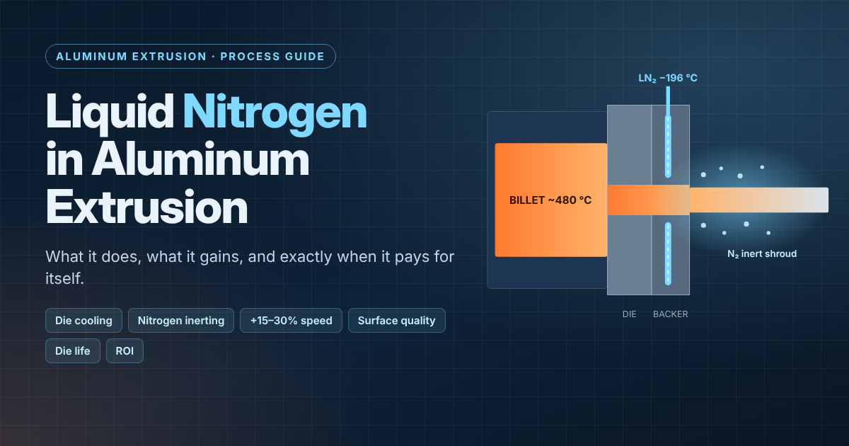
Liquid Nitrogen in Aluminum Extrusion: Benefits, Alloys, Profiles and When It Pays Off
-
 Mohamed Aboelfotouh
- Sector : Aluminum Extrusion
- Nov. 15, 2026, 8:06 p.m.
Every extruder knows the moment: the press has pressure to spare, the puller can run faster, but the profile starts tearing at the corners, die lines appear, or the anodizer sends back streaky lengths. The press is not limited by force, it is limited by heat at the die bearing. Liquid nitrogen (LN2) is the most widely used tool for pushing that ceiling up.
This guide explains what LN2 actually does inside the tooling stack, which benefits are real, which alloys and profile families justify it, and how to calculate whether it pays for itself on a specific die.
1. What is liquid nitrogen die cooling?
Liquid nitrogen is nitrogen condensed at −196 °C. In extrusion it is used in two related ways:
| Method | Nitrogen state | Where it goes | Main effect |
|---|---|---|---|
| Nitrogen shrouding (inerting) | Gas | Platen / bolster area around the die exit | Low-oxygen zone around the hot profile → less oxidation and pick-up |
| Liquid nitrogen die cooling | Liquid → gas | Channels machined on the die exit face or backer, close to the bearing | Removes heat from the bearing zone and leaves as inert gas over the profile |
Die cooling gives both effects at once: the liquid boils inside the channel and absorbs heat (roughly 200 kJ per kg just to boil, more as the cold gas warms up), then the gas is directed through small exit holes onto the profile surface as an inert shroud.
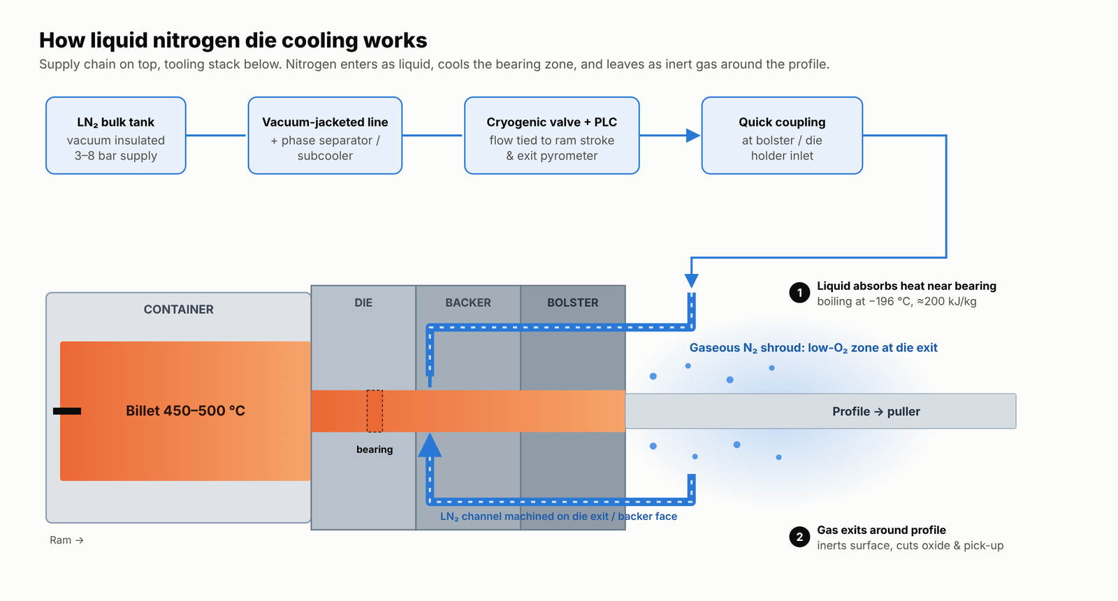
The supply chain is simple: bulk LN2 tank (vacuum insulated, delivering at a few bar, typically ≈3–8 bar) → vacuum-jacketed line with a phase separator or subcooler (so the die receives liquid, not flash gas) → cryogenic valve controlled by the press PLC → quick coupling at the bolster or die holder → channel in the die/backer.
2. Why heat limits extrusion speed
Deformation work and friction in the bearing convert most of the ram energy into heat. The faster the ram, the hotter the profile exits the die. For each alloy there is an exit-temperature ceiling where defects start:
- Hot tearing / speed cracks at corners and thin tips (incipient melting).
- Pick-up and die lines as aluminum adheres to an overheated bearing.
- Oxide streaks and dull surface, visible after anodizing.
- Bearing softening and loss of the nitrided layer, which accelerates wear.
Cooling the bearing lowers the exit temperature at a given speed, so the same ceiling is reached at a higher ram speed.
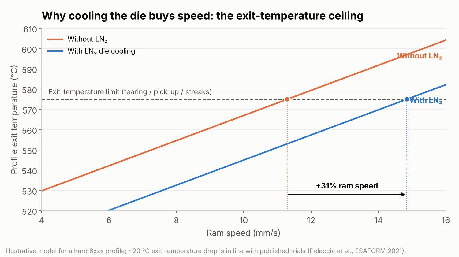
In a published industrial trial on a hollow 6060 profile, full LN2 flow reduced the profile exit temperature by about 20 °C (from 560 to 540 °C), while extrusion load rose only slightly (≈19.1 → 19.9 MN). That is the trade in one line: a few percent more pressure for a meaningful drop in exit temperature.
3. The benefits — and the realistic numbers
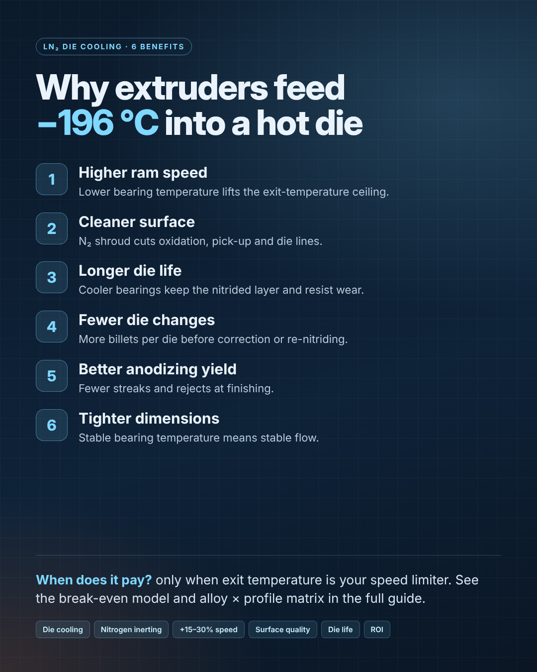
- Higher extrusion speed. Gas suppliers quote gains from 10% up to 50%. On dies that are genuinely temperature-limited, 15–30% is a realistic planning range. On dies limited by something else, the gain is close to zero.
- Better surface quality. The inert gas reduces oxidation at the die exit; bright and anodizing-grade profiles show fewer streaks, die lines and pick-up marks.
- Longer die life. A cooler bearing holds its nitrided layer longer and wears more slowly, so more billets run between corrections and re-nitriding.
- Fewer die changes and longer batches. A direct consequence of (3), plus less downtime for polishing.
- Fewer rejects at finishing. Better surface at the press means fewer rejects at anodizing and powder coating.
- More stable dimensions. A stable bearing temperature means more stable metal flow along the billet.
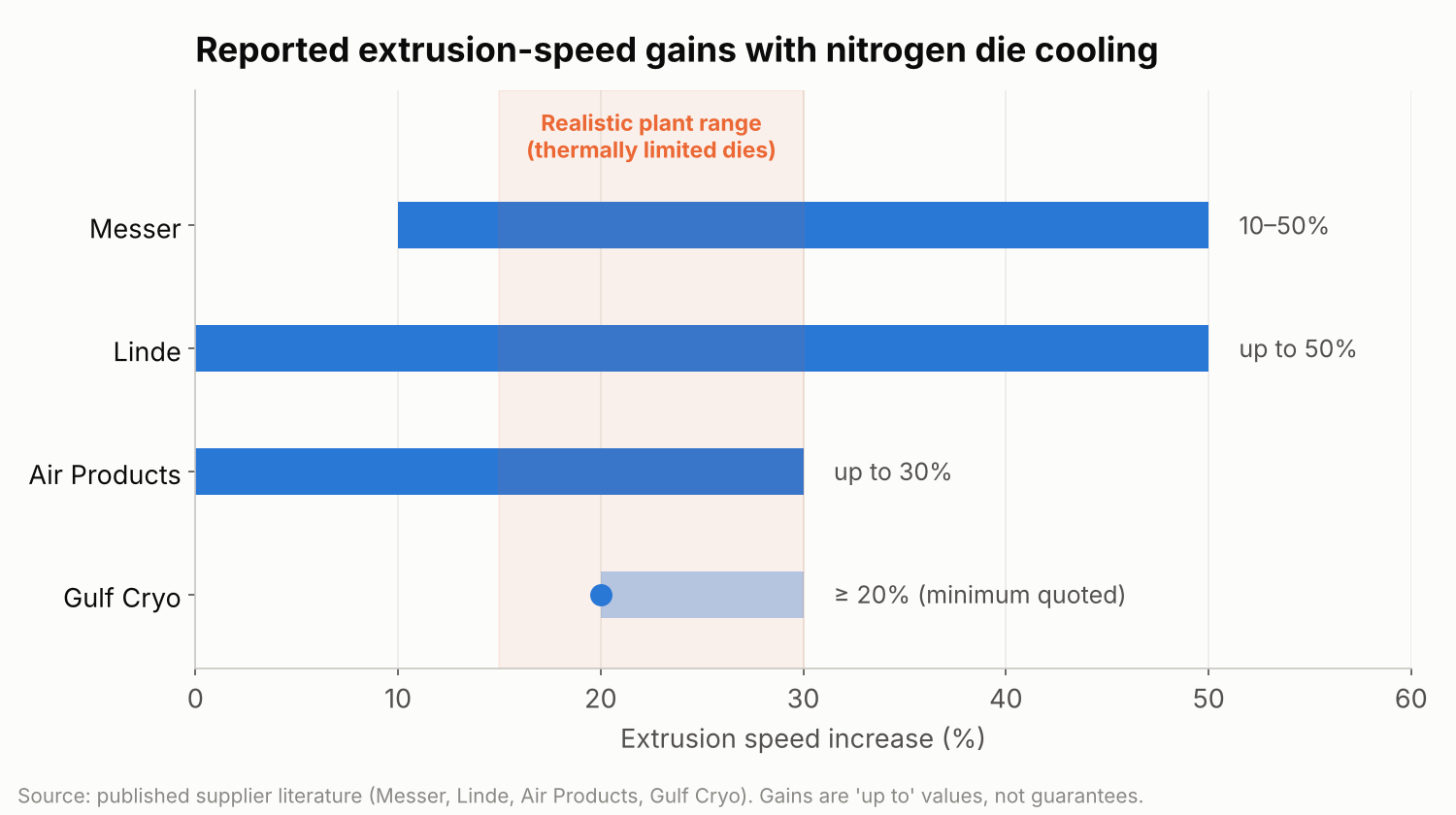
Treat supplier numbers as ceilings, not promises. One gas supplier's own technical paper notes that when die shrouding is implemented correctly its value exceeds the nitrogen cost by roughly $50–100 per press-hour — and spends most of its pages on why many plants don't get there (leaks, poor distribution on multi-hole dies, too many different shapes, insufficient flow).
4. Which alloys benefit most
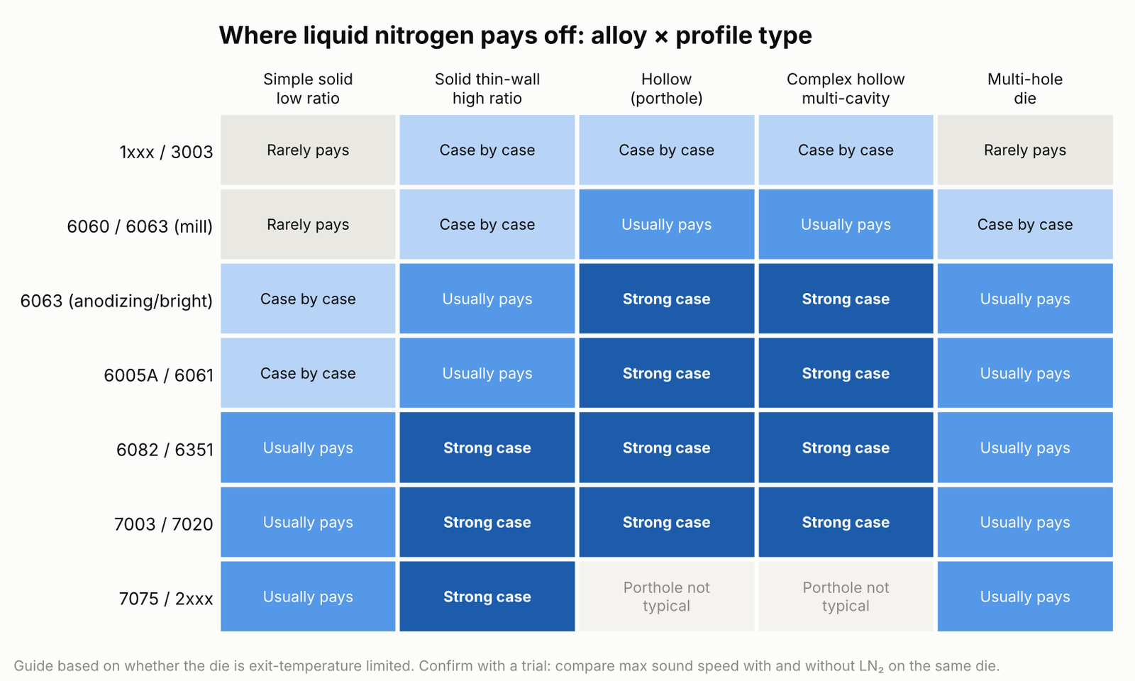
The rule is simple: the narrower the gap between extrusion temperature and the alloy's incipient-melting point, the more LN2 is worth.
| Alloy group | Typical speed limiter | LN2 value |
|---|---|---|
| 1xxx, 3003 | Press/puller speed, handling | Low — rarely the thermal limit |
| 6060 / 6063 (mill finish) | Mixed; often handling or quench | Moderate — mainly on hollows |
| 6063 bright / anodizing | Surface defects at high speed | High — surface is the product |
| 6005A / 6061 | Exit temperature + quench | High |
| 6082 / 6351 | Exit temperature (tearing) | Very high |
| 7003 / 7020 | Exit temperature (narrow window) | Very high |
| 7075 / 2xxx (hard alloys) | Exit temperature, very slow speeds | Very high on solid profiles |
Quench check: for 6005A, 6061 and 6082 a faster press also needs enough quench capacity. If your water/air quench cannot follow the higher speed, mechanical properties suffer and LN2 moves the bottleneck instead of removing it.
5. Which profiles benefit most
Profile geometry decides how much heat is generated and how sensitive the surface is:
- High extrusion ratio (roughly above 40): more deformation work, more heat.
- Thin walls and sharp tips: first to tear at high exit temperature.
- Hollow porthole dies: the weld chamber and long metal path generate extra heat — the classic LN2 application.
- Complex hollow / multi-cavity profiles: strong case, but the channel must be balanced around all cavities.
- Multi-hole dies: benefit, but uneven nitrogen distribution between holes is a common failure; one hole runs cooler and faster than the others.
- Simple, chunky, low-ratio solids: rarely temperature-limited; little to gain.
6. When is it cost-effective? A break-even model
LN2 is a running cost. It pays only when the extra output (and saved scrap) is worth more than the nitrogen plus the channel machining.
Per press-hour:
- Nitrogen cost = m × P (m = LN2 consumption in kg/h while extruding, P = price per kg)
- Value of speed gain = Q × g × M (Q = baseline net output in t/h, g = speed gain as a fraction, M = contribution margin per extra tonne)
- Other savings = S (fewer surface rejects, fewer die corrections, per hour)
Break-even speed gain:
gBE = (m × P − S) / (Q × M)
Worked example (replace with your own figures):
m = 120 kg/h, P = 0.20 USD/kg → nitrogen = 24 USD/h. S = 6 USD/h. Q = 1.2 t/h, M = 120 USD/t → Q × M = 144 USD/h per 100% gain.
gBE = (24 − 6) / 144 = 12.5%. If a trial shows a 20% gain, the die earns ≈ 11 USD per press-hour net; at 4,000 extrusion hours a year that is ≈ 44,000 USD for one press.
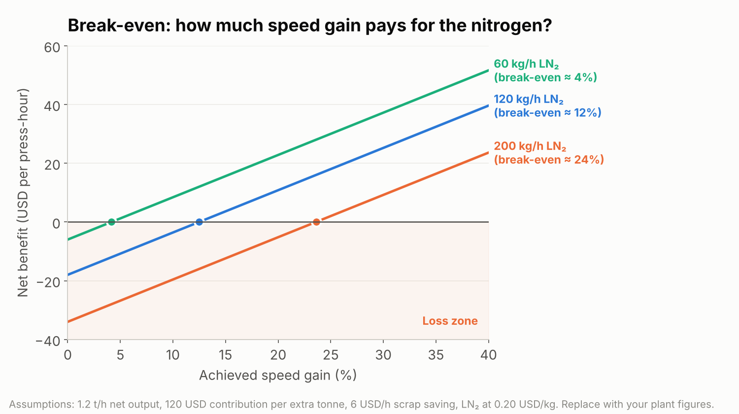
Add the tooling cost: channel machining is a one-off per die. Divide it by the tonnes the die will produce in its life. For long-running dies this is usually a few USD per tonne; for a die that will run 5 tonnes once, it can wipe out the whole benefit.
LN2 usually pays when:
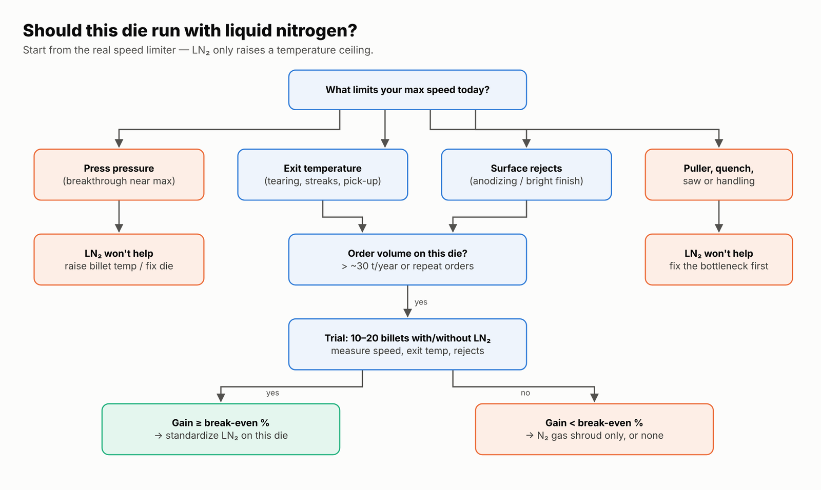
- the die is exit-temperature limited (proven by trial, not assumed);
- the order is repeat or high-volume (as a rough guide, tens of tonnes per year on that die);
- the press has pressure headroom (cooling raises load a few percent);
- downstream (puller, quench, saw, stacking) can absorb the higher speed;
- surface quality has a price (anodizing, bright finish, visible architectural faces).
It usually does not pay when the press is pressure-limited (cooling makes it worse — raise billet temperature or correct the die instead), the run is short, the profile is a simple solid in a soft alloy, or the plant has no closed-loop control and nitrogen flows at full valve all shift.
7. Die design rules for LN2 channels
The channel design decides most of the result. Research groups that optimized channel layouts showed that even modest geometry changes improve cooling while cutting nitrogen consumption. Practical rules:
- Put the channel on the die exit face or backer, following the profile contour at a consistent distance from the bearing — close enough to extract heat, far enough not to weaken the die or cause thermal shock.
- Cool where the heat is: thin tips, long bearings, tongues and areas downstream of the weld chamber. Uniform cooling of a non-uniform heat map just creates new gradients.
- Keep it symmetric and balanced. Over-cooling one side causes distortion: one trial measured a ≈60 °C difference across the die at full valve, enough to bend the profile and stress the die.
- Direct the exhaust gas onto the profile with small transfer holes so the same nitrogen also does the inerting.
- Standardize the inlet position and coupling across your die family so any die can connect in seconds — mismatched grooving between dies from different toolmakers is a known efficiency killer.
- Avoid bridges and high-stress zones on porthole dies; never let a channel reduce the section that carries the bridge load.
- Document the channel on the die drawing (inlet position, groove size, exit holes) so corrections and copies keep it.
8. Operating it correctly
- Flow only while extruding. Open the valve after breakthrough, close it at the end of the stroke; idle flow is pure cost.
- Close the loop on exit temperature. A pyrometer at the die exit controlling the valve gives stable temperature with the least nitrogen.
- Increase speed in steps during the trial (e.g., +5% per billet) and record exit temperature, extrusion pressure (bar), surface and dimensions.
- Watch the pressure headroom. If container pressure is already near the press maximum, cooling may cause a sticker.
- Measure consumption from tank level per shift and divide by tonnes produced — kg LN2 per tonne is the KPI to track per die.
- Maintain the system: check couplings and seals for leaks, ice build-up, and blocked exit holes after every die clean.
Safety
- Nitrogen displaces oxygen: install oxygen monitors near the press pit and any enclosed space.
- −196 °C causes cold burns: face shield and cryogenic gloves when connecting lines.
- Liquid trapped between two closed valves expands enormously: every line section needs a pressure relief valve.
9. Trial plan: prove it on one die before you buy for all
- Pick a die with a known temperature problem (tearing, die lines or anodizing rejects) and repeat orders.
- Machine the channel; record the cost.
- Run 5–10 billets without LN2 at the current best speed — record ram speed, exit temperature, pressure, defects.
- Run 10–20 billets with LN2, stepping speed up until the same defect limit is reached.
- Measure LN2 kg used, tonnes produced, rejects.
- Put the numbers into the break-even formula. If g ≥ gBE with margin, standardize LN2 on that die and the die family.
10. FAQ
Liquid nitrogen, gaseous nitrogen or a nitrogen generator?
Gas from a generator or cylinders is enough for shrouding only. Real die cooling needs liquid. Plants that only need surface protection on soft alloys often stop at gas.
Does LN2 change mechanical properties?
It allows higher speed at the same exit temperature, which is what controls structure. Suppliers report finer grain and better properties; research on 6060 at elevated ram speeds with LN2 cooling is ongoing. Always verify properties at the new speed — especially quench-sensitive alloys.
Can it replace a good die design?
No. LN2 raises a thermal ceiling. A die with unbalanced flow or wrong bearing lengths will still produce defects — just faster.
Is it environmentally acceptable?
Nitrogen is taken from the air and returns to it; the main footprint is the electricity used to liquefy it. The real environmental gain is higher output per kWh of press time and less scrap.
Key takeaways
- LN2 cools the die bearing and shields the profile with inert gas.
- It only increases speed when exit temperature is the limiter — prove it with a trial.
- Strongest case: 6082, 6005A/6061, 7xxx, bright/anodizing 6063, hollow and high-ratio profiles, repeat orders.
- Use the break-even formula gBE = (m·P − S)/(Q·M) per die, not per plant.
- Good channel design and flow control decide whether nitrogen is an investment or an expense.
References
- Air Products — Nitrogen die cooling: an innovative concept for aluminium extrusion (brochure 330-18-006).
- Air Products — Intelligent Nitrogen Die Cooling System for aluminium extrusion (330-22-001).
- R. Hewertson, Air Products — Factors affecting nitrogen efficiency in aluminum extrusion processes (334-13-004).
- Messer — Aluminum extrusion application page.
- Linde — Aluminum die cooling application page.
- Gulf Cryo — Liquid nitrogen aluminium extrusion process.
- R. Pelaccia, M. Negozio, B. Reggiani, L. Donati, L. Tomesani — Analysis and optimization of cooling channels performances for industrial extrusion dies, ESAFORM 2021.
- R. Pelaccia et al. — Assessment of the optimization strategy for nitrogen cooling channel design in extrusion dies, Key Engineering Materials 926.
- E. Giarmas et al. — Mechanical evaluation of 6060 aluminum alloy under elevated extrusion ram speed using liquid nitrogen die cooling, Key Engineering Materials 1048.
- T.J. Ward et al. — The effects of nitrogen — liquid and gaseous — on aluminum extrusion productivity, JOM 36 (1984).
Share Article
Related Articles