Bearing Length Rules for Balanced Metal Flow
-
 Mohamed Aboelfotouh
- Sector : Aluminum Extrusion
- Oct. 2, 2026, 4:08 p.m.
In an extrusion die, every part of the profile opening must release metal at the same speed. If one wall runs faster than its neighbour, the profile bends, twists, waves or tears. The bearing, the short land that gives the profile its final shape, is the designer's main tool for equalizing speed. This article explains how bearing length controls flow, gives starting values, and lists the factors that lengthen or shorten each bearing.
How the bearing controls speed
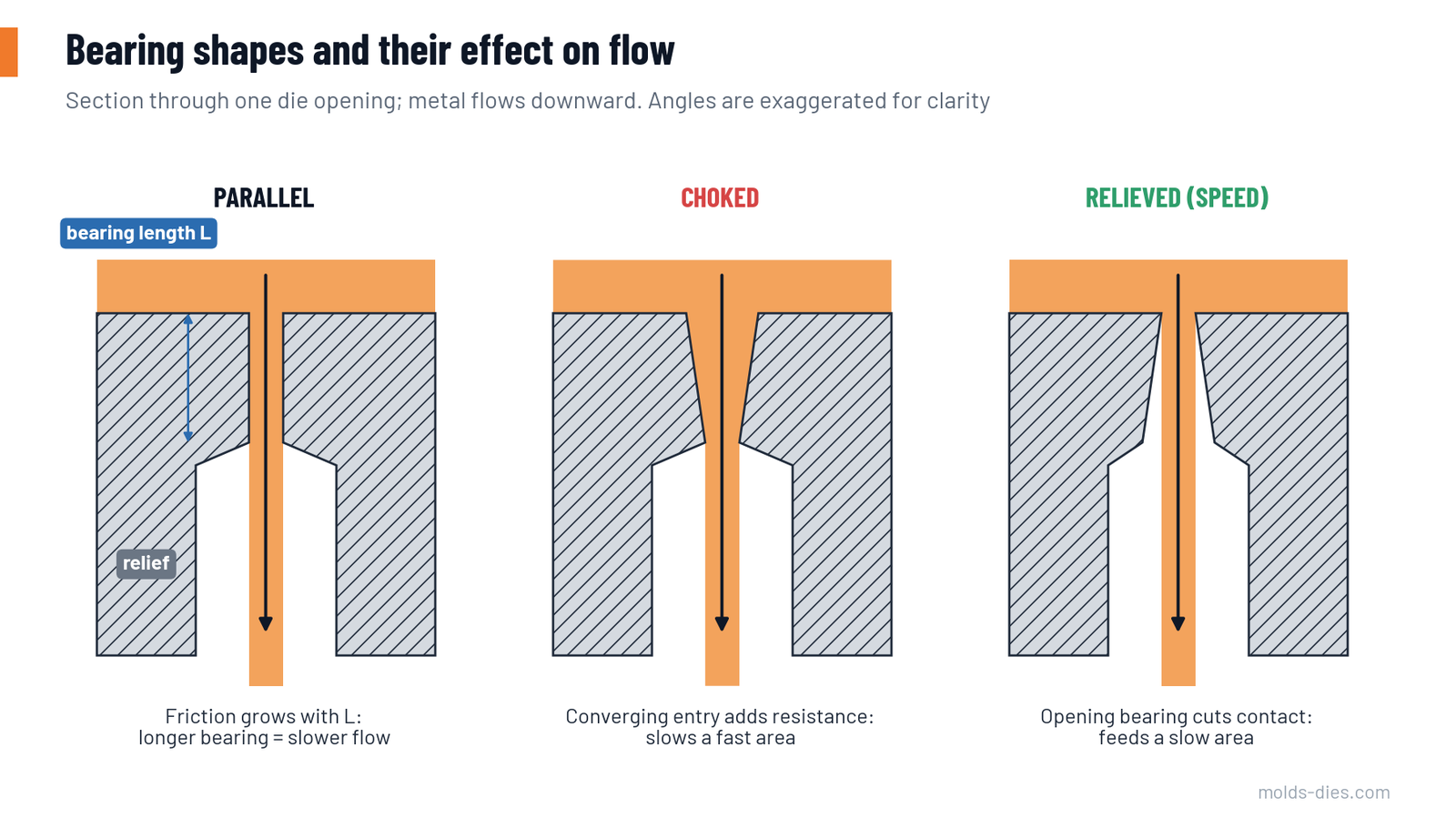
Aluminum sticks to the bearing surface and is sheared as it passes. The friction force grows with the length of the bearing, so a longer bearing slows the metal and a shorter one lets it run faster. Three shapes are used.
| Bearing shape | Effect | Use |
|---|---|---|
| Parallel | Friction proportional to length | Normal design; speed is set by length |
| Choked (converging toward the exit) | Extra resistance; metal is slowed strongly | Fast areas, thick sections, corrections |
| Relieved (opening toward the exit) | Contact only at the entry edge; metal is speeded up | Slow areas, thin tips, corrections |
The angles involved are small, from a fraction of a degree to about two degrees, and their effect is large. Behind the bearing, the die is undercut (relief) so the profile touches nothing after it leaves the bearing.
Why the speed is uneven in the first place
Without bearing control, metal would leave the die at different speeds because:
- Thick walls flow more easily than thin walls. Thin sections have more friction surface per unit of area.
- Metal near the centre of the billet flows faster than metal near the container wall, where friction against the liner holds it back.
- Free ends and tips are slow. They are fed from one side only and have friction on three sides.
- In hollow dies, areas under a bridge are slow and areas directly in front of a port are fast.
- In multi-hole dies, the openings nearer the centre run faster than those nearer the edge.
Bearing lengths are assigned to cancel these differences.
Starting values
For 6063-type alloys, a workable starting procedure is:
- Find the slowest point of the profile: usually the thinnest wall, at a free end, farthest from the die centre. Give it the shortest bearing, typically 2–3 mm and not less than about 2 mm, which is the practical minimum for strength and wear.
- Increase the bearing in proportion to wall thickness. A common starting ratio is a bearing length of about 2 to 3 times the wall thickness.
- Increase the bearing toward the die centre, and reduce it toward the edge of the die.
- Reduce the bearing at tips and free ends, typically by 20–30 % compared with the same wall away from the end.
- Limit the maximum. Beyond roughly 10–15 mm, extra length adds little control and increases heat and pick-up. If a section still runs fast with a long bearing, use a choke or restrict its feed instead.
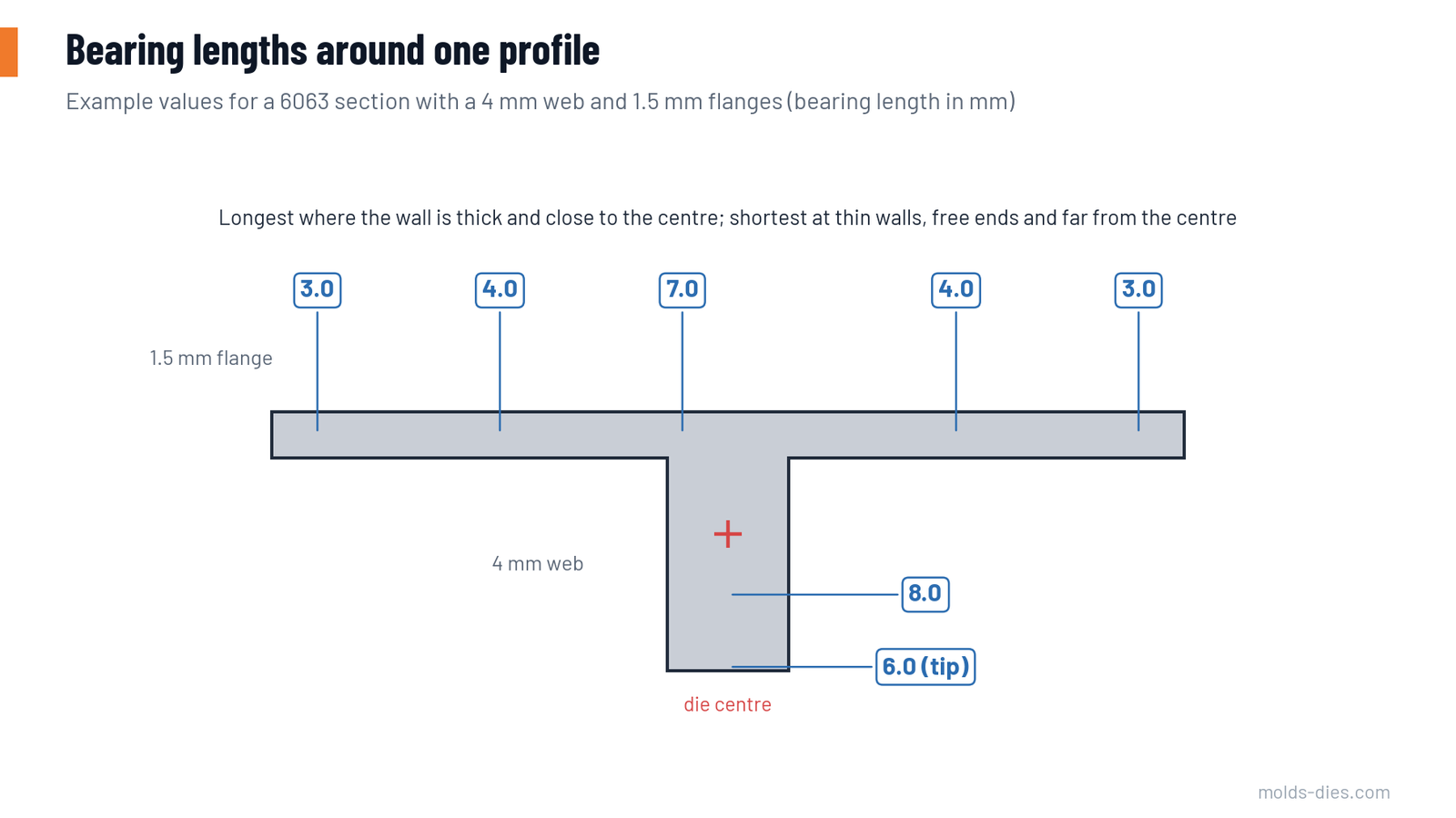
In the example, the 1.5 mm flange ends get 3.0 mm, the flange grows to 4.0 mm as it approaches the centre, the 4 mm web gets 8.0 mm, and the free tip of the web is reduced to 6.0 mm. The junction is blended at 7.0 mm.
Factors that change the bearing
| Factor | Bearing should be | Reason |
|---|---|---|
| Thicker wall | Longer | Flows more easily |
| Thinner wall | Shorter | Flows with difficulty |
| Closer to die centre | Longer | Centre of billet flows fastest |
| Closer to container wall | Shorter | Liner friction slows the metal |
| Free end, tip, sharp corner | Shorter | Fed from one side only |
| Junction of two or more walls | Longer | Large local feed; tends to run ahead |
| Next to a screw boss or heavy mass | Longer on the boss, normal on the wall next to it | Mass runs fast and drags the wall |
| Under a bridge (hollow die) | Shorter | Shadowed from the metal stream |
| Opposite a port (hollow die) | Longer | Directly fed |
| Outer holes of a multi-hole die | Shorter than inner holes | Position in the billet |
Transitions between different lengths
Abrupt steps between two bearing lengths cause streaks that show after anodizing and create a line where the profile can tear. Rules:
- Blend from one length to the next over a distance, not at a single point. A slope of about 30–45° on the bearing back edge is common.
- Keep the difference between adjacent bearing lengths moderate; if a large difference is needed, the feed (pocket or port) should be changed instead.
- Put transitions at corners or junctions where possible, not in the middle of a visible flat face.
- On the two sides of one wall, keep the bearing lengths equal, or the wall will curve toward the longer side.
Bearing is not the only control
When the wall thickness ratio in one profile is large, bearing length alone cannot balance the flow. Use the feed in front of the bearing:
| Tool | How it works | Typical use |
|---|---|---|
| Pocket (pre-chamber) | A recess in front of the opening, wider over slow areas and tight over fast ones | Thin walls far from the centre; billet-to-billet welding in flat dies |
| Feeder plate | A separate plate that spreads metal beyond the container diameter or directs it to thin areas | Wide profiles, thin flanges |
| Port size and position (hollow dies) | More port area for thin or distant walls | Balancing hollow sections |
| Choke on the bearing entry | Local brake | Heavy sections and bosses |
| Position of the profile on the die | Moves a thin wall toward the centre and a thick wall outward | Layout stage, before any detail |
A good layout and feed design leave the bearings with only fine adjustment to do. A die that depends on extreme bearing differences is hard to correct and sensitive to temperature and speed.
Manufacturing quality of the bearing
A correct length on the drawing only works if the bearing is made correctly.
| Feature | Requirement |
|---|---|
| Squareness | Bearing surface parallel to the extrusion direction unless a choke or relief is specified |
| Flatness and straightness | No barrel or hollow shape along the bearing; check with a straight edge and light |
| Surface | Polished in the extrusion direction; nitrided |
| Entry edge | Sharp and uniform, without accidental rounding, which acts as a choke |
| Relief | Clean undercut directly behind the bearing so the profile cannot drag |
From design to trial
- Lay out the profile on the die with the thin sections toward the centre where possible.
- Assign bearing lengths using the starting values and the table of factors.
- Use a calculator or flow simulation to check the balance. The Bearing Length Calculator on this site gives a first estimate.
- Make the bearings slightly long where you are unsure: at the press it is easier to relieve a bearing than to add steel.
- At the first trial, read the nose piece, correct, and record the final bearing lengths on the die drawing so the next die of the same family starts from proven values.
Common mistakes
| Mistake | Result |
|---|---|
| Same bearing length all around a profile with mixed walls | Thick walls run ahead; profile twists or waves |
| Sudden bearing steps | Streaks after anodizing |
| Bearings below 2 mm | Rapid wear, unstable dimensions |
| Very long bearings to hold back a heavy section | Heat, pick-up; little extra control |
| Unequal bearings on the two faces of a wall | Wall curves |
| Not recording corrections | The same trial work is repeated on every new die |
Key takeaways
- Longer bearing slows the metal; shorter bearing, or a relieved bearing, speeds it up.
- Start from the slowest point with 2–3 mm, scale with wall thickness at about 2–3 times the wall, lengthen toward the centre and shorten at free ends.
- Blend all transitions and keep both sides of a wall equal.
- Use pockets, feeders and layout for large flow differences, and the bearing for fine balance.
Related Articles
The Aluminum Extrusion Process & Types
Aluminum extrusion process explained with an overview of extrusion dies including solid, hollow, semi-hollow, container, and seamless dies used to produce aluminum profiles.
Billet Temperature, Ram Speed and Exit Temperature: The Process Window
How billet temperature, ram speed and exit temperature limit each other in aluminum extrusion, and how to find the fastest safe operating point.
Die Correction at the Press: Reading the Nose Piece
How to read the first extruded length (nose piece) and decide the correction: where to slow the flow, where to speed it up, and how much to change.
Porthole Die Design: Ports, Bridges and Welding Chamber
Design rules for porthole (hollow) aluminum extrusion dies: number and shape of ports, bridge strength, welding chamber height and mandrel stability.
Extrusion Defects: Die Lines, Pick-Up, Tearing and Their Fixes
The most common aluminum extrusion defects — die lines, pick-up, tearing, blisters, weld problems and dimensional errors — with causes and corrective actions.
Aluminum Extrusion Die Design Considerations
Discover the key considerations for aluminum extrusion die design, including material selection, die geometry, cooling, and stress analysis