Porthole Die Design: Ports, Bridges and Welding Chamber
-
 Mohamed Aboelfotouh
- Sector : Aluminum Extrusion
- Oct. 2, 2026, 4:09 p.m.
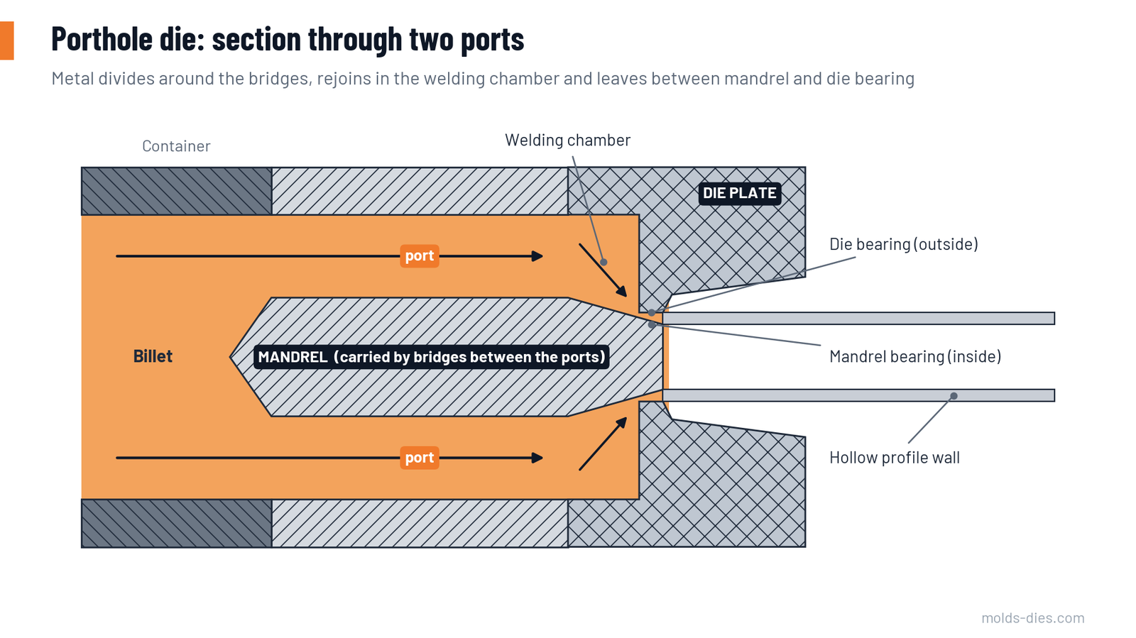
Hollow aluminum profiles such as tubes, window frames and heat-sink housings are extruded through porthole dies. The billet is split into several streams, the streams pass around a mandrel that forms the inside of the profile, and they weld together again in the solid state before leaving the die. The quality of those welds and the stability of the mandrel depend on three elements: the ports, the bridges and the welding chamber. This article gives the design rules for each.
How a porthole die works
| Component | Function |
|---|---|
| Mandrel (upper die) | Carries the core that forms the inside shape. Contains the ports and bridges |
| Ports | Openings through the mandrel that let the metal pass to the welding chamber |
| Bridges (webs) | The steel between the ports. They hold the core in position against the extrusion pressure |
| Welding chamber | The space in the die plate where the separate streams rejoin around the core and weld under pressure |
| Die plate (lower die, cap) | Forms the outside shape and carries the outside bearing |
| Backer and bolster | Support the die plate against bending |
Two kinds of weld result. Seam welds run along the whole length of the profile, one behind each bridge. Transverse (charge) welds form where a new billet joins the metal of the previous one left in the ports and chamber.
Ports
Number and position. Each bridge creates a seam weld, so the number and position of the ports decide where the welds lie in the profile.
- Place the bridges so the seam welds fall at corners, at thick junctions or on non-visible faces. Avoid the middle of a decorative or highly loaded wall.
- Use the smallest number of ports that supports the core safely: two for small tubes and simple rectangles, three or four for most sections, more for wide or multi-cavity profiles.
- For profiles with several cavities, every core needs its own support, and ports must feed the inner walls between cores as well as the outer walls.
Size and balance. The ports control how much metal reaches each part of the profile.
- Give each port an area in proportion to the profile area it feeds. A port feeding a thick wall or a long perimeter needs more area.
- Ports farther from the centre of the billet receive slower metal and need to be larger than central ports feeding the same area.
- Keep the layout symmetrical where the profile allows. Unequal pressure on opposite sides of the core pushes it sideways and makes one wall thin and the opposite wall thick.
- Stay inside the circle the container can feed, with a margin to the liner so the oxidized billet skin is not drawn into the ports.
Shape. Chamfer or radius the port entry so metal enters smoothly. Many designs incline the outer port walls a few degrees outward toward the welding chamber to spread metal to the outer walls of wide profiles.
Bridges
The bridges take the full load on the core: the extrusion pressure on the core's projected area, plus friction. They fail by bending or shear cracking at the roots if they are undersized, and they disturb the flow if they are oversized.
| Feature | Rule | Reason |
|---|---|---|
| Width (seen from the billet side) | As narrow as strength allows | A wide bridge leaves a large shadowed zone that the welding chamber must refill |
| Depth (in the extrusion direction) | Generous; this is where bending strength comes from | Stiffness rises quickly with depth |
| Entry side | Rounded or chamfered | Splits the metal with less pressure and less dead zone |
| Exit side (under the bridge) | Tapered to a narrow edge (teardrop or roof shape) | Lets the two streams meet soon and at high pressure |
| Roots (where bridge meets core and die ring) | Large fillet radii, polished | The highest tensile stress in the die is here; sharp corners start cracks |
| Core attachment | Short, stiff connection between bridges and core | Limits elastic deflection and core shift |
Check the bridge stress and the core deflection by calculation or simulation for every new design, using the highest breakthrough pressure the press can deliver, not the average running pressure.
Welding chamber
In the chamber the streams from adjacent ports meet under the bridge and are pressed together. Clean metal surfaces that have just been formed weld in the solid state if pressure, temperature and contact time are sufficient.
| Parameter | Effect of increasing it |
|---|---|
| Chamber height (distance from the underside of the bridge to the bearing) | More time and higher pressure for welding; better welds. Also higher extrusion pressure and more metal left in the die |
| Chamber width around the core | Easier flow under the bridge. Too wide reduces the pressure at the weld |
| Bridge width | Needs a higher chamber to refill the shadow |
Practical rules:
- Increase chamber height with bridge width. A common first check is a chamber height of at least half the bridge width to about equal to it, and commonly in the range of 15–25 mm for medium press sizes.
- For thick-walled profiles and for alloys that weld less easily (6082, 6061, and above all 7xxx), use a higher chamber than for 6063.
- Shape the chamber floor so there are no dead corners where metal stagnates and later breaks loose as streaks.
- Keep the chamber outline close to the profile outline, with more space where walls are thin and far from the ports.
Bearings in a porthole die
- The profile has two bearings: on the die plate (outside) and on the core (inside). The core bearing usually starts slightly before and ends slightly after the die bearing, by about 1 mm, so the wall is always supported on the inside.
- Use shorter bearings under the bridges, where metal arrives slowly, and longer bearings opposite the ports.
- Balance the inside and outside bearings of each wall, or the wall will curve.
Steel, heat treatment and fit
| Item | Recommendation |
|---|---|
| Steel | H13-type hot-work tool steel, premium quality for mandrels |
| Hardness | About 46–50 HRC; mandrels with slender bridges at the lower end for toughness |
| Surface | Nitrided bearings; re-nitride after a set number of runs |
| Mandrel-to-die location | Dowels and a register diameter with small clearance; the two parts must seat flat over the full contact face |
| Support | Backer opening as close to the profile as practical; flat, undamaged bolster |
Weld quality: what the die cannot fix alone
| Factor | Requirement |
|---|---|
| Cleanliness | No lubricant, oxide or dirt in the streams. Keep die lubricant away from the die face; clean the container |
| Temperature | Billet and die hot enough for bonding; a cold die at start-up gives poor first welds |
| Speed | High speed shortens the contact time; reduce it if welds are marginal |
| Billet-to-billet weld | Shear the butt cleanly; cut off the transition length after each new billet |
Test seam welds with a drift expansion test: push a cone into a short length of the profile and check that it does not split along the weld lines. Test at the start and end of an extrusion and after any change to the die.
Typical problems and their source
| Symptom | Likely cause in the die | Action |
|---|---|---|
| Wall thickness uneven around the profile | Core shift from unbalanced ports or weak bridges | Balance the ports; stiffen the bridges |
| Profile splits along a line in the expansion test | Low welding pressure or contaminated weld | Increase chamber height; check lubrication practice |
| Streak on an anodized face behind a bridge | Seam weld on a visible face | Move the bridge; raise chamber height |
| Cracks at bridge roots after few billets | Small root radius, hardness too high, cold start | Enlarge radii; check heat treatment; preheat fully |
| High breakthrough pressure | Small ports, high chamber, long bearings | Open the ports; check billet and die temperature |
Common mistakes
| Mistake | Result |
|---|---|
| Port areas equal although the walls they feed are different | Unbalanced flow, core shift |
| Bridge underside left flat | Dead zone, weak weld, streak |
| Sharp corners at bridge roots | Early fatigue cracks |
| Chamber kept shallow to reduce pressure | Welds fail the expansion test |
| Die loaded below working temperature | First billets with poor welds; risk of bridge cracking |
Key takeaways
- Ports decide where the seam welds lie and how the metal is shared between walls: size them in proportion to the area fed and keep them balanced.
- Bridges must be narrow, deep, tapered on the exit side and generously radiused at the roots.
- The welding chamber provides the pressure and time for welding: raise it for wide bridges, thick walls and harder alloys.
- Verify bridge stress and core deflection before cutting steel, and prove weld quality with an expansion test.
Related Articles
The Aluminum Extrusion Process & Types
Aluminum extrusion process explained with an overview of extrusion dies including solid, hollow, semi-hollow, container, and seamless dies used to produce aluminum profiles.
Billet Temperature, Ram Speed and Exit Temperature: The Process Window
How billet temperature, ram speed and exit temperature limit each other in aluminum extrusion, and how to find the fastest safe operating point.
Die Correction at the Press: Reading the Nose Piece
How to read the first extruded length (nose piece) and decide the correction: where to slow the flow, where to speed it up, and how much to change.
Bearing Length Rules for Balanced Metal Flow
How to set bearing lengths in an aluminum extrusion die: starting values, the factors that change them, and the rules that keep metal flow balanced.
Extrusion Defects: Die Lines, Pick-Up, Tearing and Their Fixes
The most common aluminum extrusion defects — die lines, pick-up, tearing, blisters, weld problems and dimensional errors — with causes and corrective actions.
Aluminum Extrusion Die Design Considerations
Discover the key considerations for aluminum extrusion die design, including material selection, die geometry, cooling, and stress analysis